Tutorial 5: Joint Drive Tuning#
Collision pairs are filtered (Tutorial 4). The next question: with how much torque and velocity can each joint move? If the simulated hand can apply more torque than the real hardware, or spin faster than the real motors, your grasps and controllers will behave differently in sim than on the robot. Conversely, limits that are too low make the hand feel weak or sluggish. In this tutorial we set the drive limits—max torque and max velocity—from the Inspire Hand specs. Stiffness and damping (how the joint responds to position commands) are tuned in Tutorial 6.
Learning Objectives#
In this tutorial, you will:
Configure mimic joints to be non-compliant for initial gains tuning.
Compute and set max joint torque derived from Inspire specifications.
Set max joint velocity directly from Inspire specifications.
Inspire Hand specs used in this tutorial (palm fingers): Max palm finger grip force 10 N; max palm finger bend speed 260 deg/s.
Prerequisites#
Complete Tutorial 4: Collider Pairs.
Open
/path/to/Inspire/module_3_end-checkpoint_1/inspire_hand.usdain Isaac Sim (or have your own filtered-pairs version open).
Module 4.1: Mimic Joints#
In the Inspire Hand model, the fingers use PhysX mimic joints to replicate the underactuated mechanism found in the real robotic hand. In this approach, a single motor drives multiple joints using a fixed gear ratio, allowing for coordinated finger movement and more realistic simulation of the physical hand.
A mimic joint links two degrees of freedom, establishing a relationship (via gear ratio and offset) so that when one joint moves, the other follows accordingly. These mimic joints can be either compliant (allowing some “softness” or flexibility, like a spring) or non-compliant (rigidly enforcing the kinematic constraint). For this tutorial, we’ll configure non-compliant mimic joints to initially tune the driven joints. (You can add compliance for “softer” mimic behavior later, if needed.)
Follow these steps to configure the mimic joints:
Open
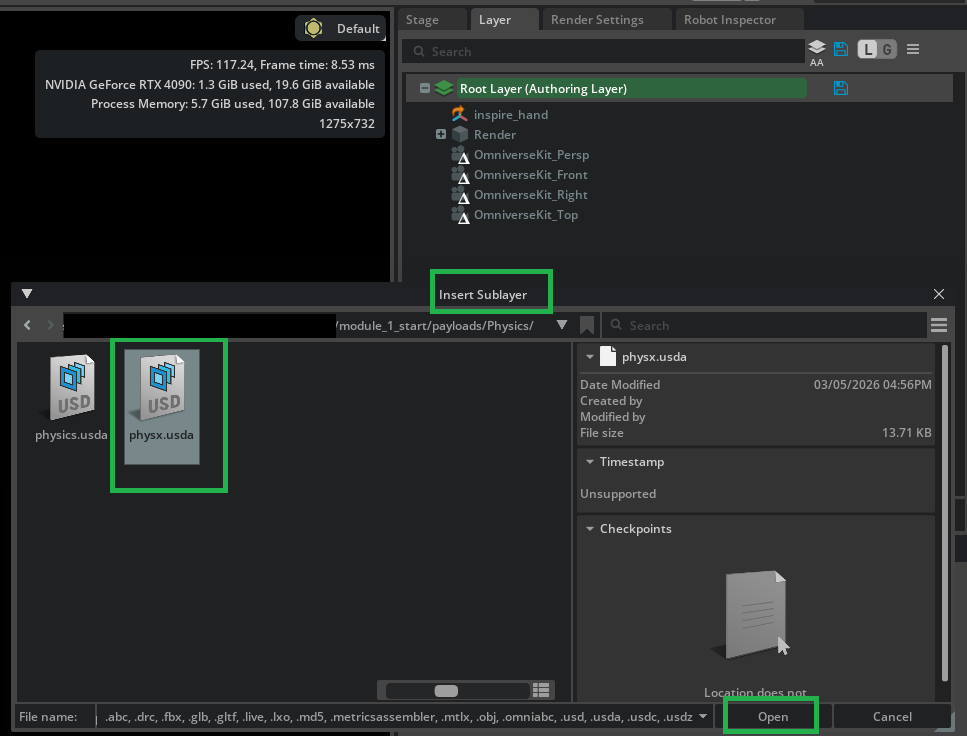
/path/to/Inspire/module_3_end-checkpoint_1/inspire_hand.usdain Isaac Sim if you haven’t already.Mimic joints are a PhysX-specific feature, so set your authoring layer to physx.usda. In the Layer tab, click the Insert Sublayer icon if the sublayer is not already there.
In the file dialog, navigate to
/path/to/Inspire/module_3_end-checkpoint_1/payloads/Physics/, selectphysx.usda, and click Open.
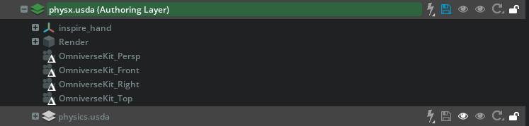
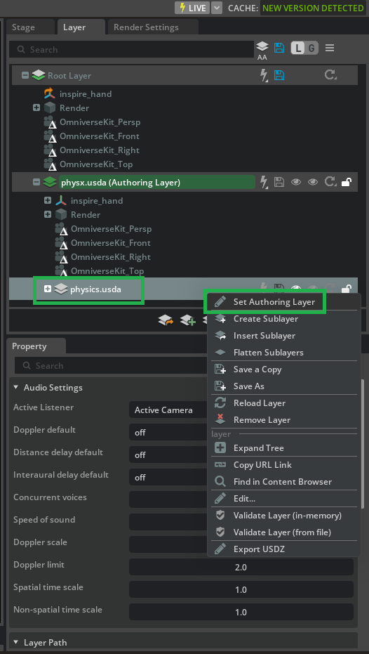
Once physx.usda appears in the layer stack, Right-click on physx.usda and select Set Authoring Layer.

You should now see the physx.usda layer highlighted green, indicating it is the active authoring layer.

In the Stage panel, multi-select the mimic joints for the Inspire Hand palm fingers (hold CTRL and left-click each):
right_thumb_3_jointright_thumb_4_jointright_index_2_jointright_middle_2_jointright_ring_2_jointright_little_2_joint

With the joints selected, go to the Property panel. Find the Mimic Joint section and set Damping Ratio to 0.0 and Natural Frequency to 0.0 to make the constraint non-compliant.

Tip
Setting natural frequency or damping ratio to 0.0 tells PhysX to make this a non-compliant mimic joint. Setting both of them to 0.0 makes the intent clear.
Click on the blue files icon next to physx.usda (Authoring Layer) to save the changes to physx.usda.
After these steps, the mimic joints in your Inspire Hand model will behave as a stiff, non-compliant mechanism, giving you precise control for gains tuning in the next module.
Module 4.2: Configure Max Joint Torque#
The maximum drive force (torque for revolute joints) caps how much force the finger can apply at the contact. Too low and the hand cannot hold the specified load; too high and you risk unrealistic forces or instability. We derive the value from the manufacturer’s grip force and the distance from joint to fingertip so the sim matches the real hand’s capability.
Torque = Force × Distance
For the palm finger, max force is 10 N. The distance between right_little_1_joint and the tip of the little finger is 0.045 m + 0.039 m.
Little finger: Torque = 10 × (0.045 + 0.039) = 0.84 Nm
There are two joints in the mimic chain, so multiply by 2:
Little finger max drive force: 0.84 × 2 = 1.68 Nm
Max Force drive parameters are a neutral physics attribute, so author on the physics.usda layer. In the Layer tab, expand the physx.usda layer.

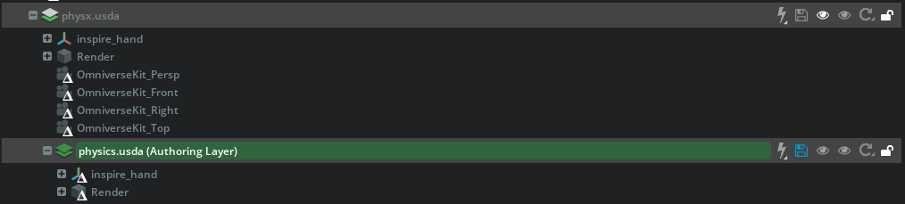
Right-click on physics.usda and select Set Authoring Layer.
You should now see the physics.usda layer highlighted green, indicating it is the active authoring layer.

In the Stage panel, find and select
inspire_hand/Physics/right_little_1_joint.In the Property panel, scroll to Drive and set Max Force to 1.68 based on our calculations.

Click on the blue files icon next to physics.usda (Authoring Layer) to save the changes to physics.usda.
Module 4.3: Apply Max Velocity#
Maximum joint velocity limits how fast the joint can move. Without a cap, the solver can command velocities that no real motor could achieve, leading to unrealistic motion or numerical instability. We set the limit from the Inspire Hand’s palm finger bend speed (260 deg/s) so the simulated hand moves within the same envelope as the hardware.
Realism — Simulated motion matches real hardware.
Stability — Avoids velocity spikes that cause instability.
Maximum joint velocity is a PhysX-specific attribute, so author on the physx.usda layer. In the Layer tab, Right-click on physx.usda and select Set Authoring Layer.
You should now see the physx.usda layer highlighted green, indicating it is the active authoring layer.
In the Stage panel, find and select
inspire_hand/Physics/right_little_1_joint.In the Property panel, scroll to Raw USD Properties, expand Advanced, and set Maximum Joint Velocity to 260 (deg/s).

Click on the blue files icon next to physx.usda (Authoring Layer) to save the changes to physx.usda.
Note
A checkpoint file with drive limits for all 6 joints derived using the same process is provided at /path/to/Inspire/module_4_end-checkpoint_2/inspire_hand.usda. Open this file before starting Tutorial 6.
Summary#
This tutorial covered:
Configuring mimic joints as non-compliant so the solver enforces the finger kinematics without adding compliance—setting you up for clean gain tuning in Tutorial 6.
Computing and setting max joint torque from Inspire Hand specs (force × distance, then × 2 for the mimic chain) so the hand’s grip capability matches the real robot.
Setting max joint velocity from specs (260 deg/s) so motion is realistic and the simulation stays stable.
Next Steps#
Continue to Tutorial 6: Joint Gains Tuning to tune drive stiffness and damping with the Gain Tuner and analyze the results.