MJCF Importer Extension#
Note
Starting from the Isaac Sim 2023.1.0 release, the MJCF importer has been open-sourced. Source code and information for contributing can be found at our Github repository. As of Isaac sim 5.0, the former dedicated repository has been deprecated, and the code has been moved to the Isaac Sim repository.
The MJCF Importer Extension Extension is used to import MuJoCo representations of robots. MuJoCo Modeling XML File (MJCF), is an XML format for representing a robot model in the MuJoCo simulator.
To access this extension, go to the top menu bar and click File > Import.
This extension is enabled by default. If it is ever disabled, it can be re-enabled from the Extension Manager
by searching for isaacsim.asset.importer.mjcf.
Conventions#
Note
Special characters in link or joint names are not supported and are replaced with an underscore. In the event that the name starts with an underscore due to the replacement, an a is pre-pended. It is recommended to make these name changes in the MJCF directly.
Refer to the Isaac Sim Conventions documentation for a complete list of NVIDIA Isaac Sim conventions.
User Interface#
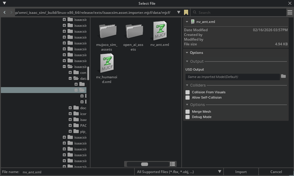
Import Options#
- USD Output: Specifies where the generated USD file will be saved. By default, this is set to “Same as Imported Model(Default)”,
which saves the USD file in the same directory as the source MJCF file. Users can click the folder icon to select a different output location.
- Colliders:
Collision From Visuals: When enabled, collision geometry is generated from the visual meshes in the MJCF file. This is useful when the MJCF file doesn’t have explicit collision geometry defined. When this option is checked, the Collision Type dropdown becomes visible.
- Collision Type: Select between:
Convex Hull: Creates a convex hull around the visual mesh.
Convex Decomposition: Decomposes the visual mesh into multiple convex pieces for more accurate collision detection.
Bounding Sphere: Uses a simple bounding sphere approximation.
Bounding Cube: Uses a simple bounding box approximation.
Allow Self-Collision: When enabled, allows the robot model to collide with itself. This can be useful for certain simulation scenarios but may cause instability if collision meshes between links are self-intersecting.
- Options:
Robot Type: Sets the
isaac:robotTypeattribute on the imported robot’s schema. Choose from: Default, End Effector, Manipulator, Humanoid, Wheeled, Holonomic, Quadruped, Mobile Manipulators, or Aerial.Base Type: Tri-state control of how the robot’s root link is anchored.
Source (default): leaves the source MJCF authoring untouched.
Fixed: adds a world-to-root fixed joint and relocates
ArticulationRootAPIto the correct ancestor prim.Mobile: removes any existing world-to-root fixed joint so the robot is free to translate and rotate.
Maps directly onto the
fix_base: bool | Nonefield onMJCFImporterConfig(None/True/False).Import Scene: When enabled, imports the MJCF simulation settings along with the model.
Merge Mesh: When enabled, merges meshes where possible to optimize the model. This can reduce the number of prims in the resulting USD file and improve performance.
Debug Mode: When enabled, activates debug mode to preserve the intermediate files and asset transformer reports
Robot Properties#
There might be many properties you want to tune on your robot. These properties can be spread across many different Schemas and APIs.
The general steps of getting and setting a parameter are:
Find which API the parameter is under. Most common ones can be found in the Pixar USD API.
Get the prim handle that the API is applied to. For example, Articulation and Drive APIs are applied to joints, and MassAPIs are applied to the rigid bodies.
Get the handle to the API. From there on, you can Get or Set the attributes associated with that API.
For example, if you want to set the wheel’s drive velocity and the actuators’ stiffness, you must find the DriveAPI:
# get handle to the Drive API for both wheels
left_wheel_drive = UsdPhysics.DriveAPI.Get(stage.GetPrimAtPath("/carter/chassis_link/left_wheel"), "angular")
right_wheel_drive = UsdPhysics.DriveAPI.Get(stage.GetPrimAtPath("/carter/chassis_link/right_wheel"), "angular")

# Set the velocity drive target in degrees/second
left_wheel_drive.GetTargetVelocityAttr().Set(150)
right_wheel_drive.GetTargetVelocityAttr().Set(150)

# Set the drive damping, which controls the strength of the velocity drive
left_wheel_drive.GetDampingAttr().Set(15000)
right_wheel_drive.GetDampingAttr().Set(15000)

# Set the drive stiffness, which controls the strength of the position drive
# In this case because we want to do velocity control this should be set to zero
left_wheel_drive.GetStiffnessAttr().Set(0)
right_wheel_drive.GetStiffnessAttr().Set(0)
Alternatively you can use the Omniverse Commands Tool Extension to change a value in the UI and get the associated Omniverse command that changes the property.
Note
The drive stiffness parameter should be set when using position control on a joint drive.
The drive damping parameter should be set when using velocity control on a joint drive.
A combination of setting stiffness and damping on a drive will result in both targets being applied, this can be useful in position control to reduce vibrations.
Note
See the Gain Tuner Extension tutorial to tune the gains for your robot.
Multi-Physics Engine Support#
The MJCF importer supports the conversion of MJCF actuator/joint data to PhysX schemas for multi-physics engine support. This allows you to use the same MJCF file with different physics engines.
The conversion is done automatically when the MJCF importer is used. You can use the Gain Tuner Extension tutorial to tune the gains for your robot with the multi-physics engine.
MJCF Attribute |
PhysX Attribute |
Notes |
|---|---|---|
MJC Actuator: gainType (fixed) |
UsdPhysics DriveAPI.gainType |
If gainType is present and is “fixed”, and bias type is “affine”, the gainPrm array is used to set the stiffness and damping. Only “fixed” gain type is supported. See explanation in the warning below. |
MJC Actuator: biasType (affine) |
UsdPhysics DriveAPI.biasType |
If biasType is present and is “affine”, and gain type is “fixed”, the biasPrm array is used to set the damping. Only “affine” bias type is supported. See explanation in the warning below. |
MJC Actuator: gainprm ([kp, 0, 0, …]) - position control |
UsdPhysics DriveAPI.stiffness |
if gainprm array is present and the first element is not 0, stiffness = gainprm[0]. Stiffness must be a positive value in USD Physics. |
MJC Actuator: gainprm ([kd, 0, 0, …]) - velocity control |
UsdPhysics DriveAPI.damping |
if gainprm array is present and the first element is not 0, damping = gainprm[0]. Damping must be a positive value in USD Physics. |
MJC Actuator: biasprm ([0, -kp, -kd, …]) - position control |
UsdPhysics DriveAPI.damping, UsdPhysics DriveAPI.stiffness |
if biasprm array is present and the second and third elements are not 0, damping = -biasprm[2], stiffness = -biasprm[1]. Stiffness and damping must be positive values in USD Physics. |
MJC Actuator: biasprm ([0, 0, -kd, …]) - velocity control |
UsdPhysics DriveAPI.damping |
if biasprm array is present and the third element is not 0, damping = -biasprm[2], stiffness = 0. Damping must be a positive value in USD Physics. |
mjc:forceRange:max |
UsdPhysics DriveAPI.maxForce |
MJCF uses min/max while PhysX uses maxForce. PhysX does not support min force ranges, so converted behavior may differ if abs(min) != max. |
mjc:frictionloss |
PhysxJointAPI.jointFriction |
Applied to joint friction attribute |
mjc:armature |
PhysxJointAPI.armature |
Sets armature parameter |
mjc:ref |
UsdPhysics DriveAPI.targetPosition |
Initial joint target position |
Warning
USD Physics uses PD controller for position control and P controller for velocity control, which is different from MJCF’s general controller formulation F = gain * control + bias, so only fixed gain type and affine bias type are supported. If the gain type or bias type is not “fixed” or “affine”, the physics drive stiffness and damping will not be created, please check the MJCF actuator attributes and adjust the gain type and bias type accordingly.
Note
Mimic joints:
The MJCF importer supports conversion of mimic (dependent) joints, allowing one joint’s motion to follow another with scaling and offset. In MuJoCo/MJCF, mimic relationships use mimicJoint plus mimicCoef to model a higher-order relationship between the follower and leader joint. The importer captures the first-order term (offset and scale) so the runtime can enforce follower = mimicCoef0 + mimicCoef1 * leader.
When importing, the mimic attributes are written through NewtonMimicAPI on the follower joint:
newton:mimicJointis a relationship targeting the leader joint.newton:mimicCoef1stores the scale factor.newton:mimicCoef0stores the offset.
The runtime consumes NewtonMimicAPI directly, so no equivalent PhysxMimicJointAPI is authored.
See source code for precise logic and usage.
Articulation Root API#
The MJCF importer applies the standard UsdPhysics.ArticulationRootAPI and the NewtonArticulationRootAPI on the root link of the MJCF file. Self-collision behavior is authored via newton:selfCollisionEnabled and consumed by the runtime directly; the PhysX-specific PhysxArticulationAPI is no longer authored.
Known Issues#
Multi-DOF Joints Between the Same Body Pair#
In USD, a joint is a kinematic constraint between two rigid bodies and locks every degree of freedom except the joint’s own axis. A revolute joint, for example, has one DOF and removes the other five.
MuJoCo treats a joint as a single degree of freedom and lets you stack several single-axis joints between the same body pair to express a multi-DOF connection. An x-axis revolute joint and a y-axis revolute joint between the same parent and child body together form a 2-DOF rotational joint. PhysX rejects this layout because it produces multiple constraints between the same body pair (a “closed articulation”).
When run_multi_physics_conversion is enabled (the default), the MJCF importer fixes this automatically in the PhysX variant after the asset transformer runs. The post-processing pass walks every joint in payloads/Physics/physx.usda, groups them by their (body0, body1) targets, retypes the first joint in each over-constrained group to a PhysicsJoint (D6) with per-axis LimitAPI/DriveAPI instances, deactivates the remaining joints via active = false, and redirects any NewtonMimicAPI.newton:mimicJoint reference at the new D6 host. All edits are confined to the PhysX overlay layer; the base physics.usda is untouched, so the MuJoCo/Newton variants still see the original per-DOF joints. As a result, a control policy trained against one variant cannot be transferred directly to the other.
Two MJCF authoring patterns produce a result the D6 cannot represent exactly:
Off-axis joints that share the same nominal
physics:axistoken. The MJCF→USD converter normalizes any vec3 axis to one of"X"/"Y"/"Z"and bakes the actual direction intolocalRot0/localRot1. If two joints in the same group end up with the same token, only the first one is folded into the D6; the second is deactivated and its DOF is dropped. A warning is logged for the dropped joint.No recognizable ``physics:axis``. The joint cannot be assigned a D6 axis and is treated the same as the duplicate-axis case (deactivated, DOF dropped).
If you want to retain every DOF and you can edit the MJCF, the manual workaround is to insert a zero-mass dummy link between the parent and child and split the multi-DOF joint into one single-DOF joint per intermediate edge.
References#
Refer to the Asset Structure for more information about the asset structure.
Tutorial#
Review Tutorial: Import MJCF.