Camera Calibration#
The Camera Calibration Tool (isaacsim.sensors.rtx.calibration extension) generates camera calibration data for deployed cameras in the scene.
Enable the Extension#
Follow the Omniverse Extension Manager guide to enable the isaacsim.sensors.rtx.calibration extension.
Open the Calibration Tool Panel#
The Calibration Tool UI will automatically be opened on the right side of the screen. It is accessible by Tools > Sensors > Camera Calibration.
Input Fields#
Place Info: A string that describes the location of the scene, including city, building, and room. This information is converted and stored in calibration.json. Review the output example for more details.
Input Format:
city=[city name]/building=[building name]/room=[room name]Example:
Input:
city=Santa Clara/building=NVIDIA Voyager/room=Visitor LobbyOutput: in
calibration.json:{ "place": [ { "name": "city", "value": "Santa Clara" }, { "name": "building", "value": "NVIDIA Voyager" }, { "name": "room", "value": "Visitor Lobby" } ], }
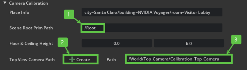
Scene Root Prim Path: The path to the root prim of the scene. This is used to approximate the top view camera’s position. The top view camera will look at the scene root prim’s center.
Floor & Ceiling Height: The floor and ceiling height values for the scene.
Note
The ceiling height adjusts the clipping range of the top view camera, making it easier to create accurate top views.
By default, the ceiling height is set to
-1, which means the top view camera’s clipping range will use its default value.By customizing the ceiling height, you can clip out prims or objects above the specified value when creating a top view camera.
Top View Camera: This camera will be used to render the top_view images.
Create: After Scene Root Prim Path is set, clicking this button will automatically generate a top view camera that looks at the scene root’s center. The top view camera will be generated under
/World/Top_Camera.Path: After clicking Create, the top view camera’s path will be shown here. You can also use this field to select existing top view cameras in the stage.
Note
The Top View Camera must be vertical to the ground and it must cover the position of all the calibration dots under
World/Calibration_Dotsand cameras under theWorld/Cameras.The Top View Camera must have a rotation of
[0,0,0]with the projection type set toorthographic.
Raycast Density: The density of the raycast. The higher this value, the more detailed the FOV contour will be. A density value of N indicates that N * N rays will be cast and they are uniformly distributed for each camera.
Default value: 100
Minimum FOV Polygon Edge Length (meter): The minimum length of edges in the polygon’s contour. Edges shorter than this length are ignored and the vertices are connected to the next point that meets this criteria. The unit is meter.
Default value: 0 (no simplification in drawing the contour)
Minimum Area of FOV Polygon Hole to Ignore: When generating data, holes in the FOV polygon that are smaller than this threshold value are ignored. Holes are the areas that are not included in the FOV polygon.
Default value: 0 (don’t ignore any holes in FOV polygons)
Create Camera View Images: Whether to include camera view images in the output folder.
Create FOV Polygon Images: Whether to render top view images with FOV polygons in the debug data folder.
Show FOV Polygon: Whether to show FOV polygons from the currently selected camera.
Output Folder Path: The path to the output folder. Click on the folder icon to select the output folder path.
Using the Camera Calibration Tool Tutorial#
To use the Camera Calibration tool. This tutorial makes use of the Isaac Sim Full Warehouse for demonstration.
Note
Stage unit must be in meters.
A valid NavMesh is required.
Enable the Extension#
Create Cameras#
Cameras under /World/Cameras are used to generate the calibration file. Ideally, the cameras are able to view the walkable area of the scene.
Tip
To add cameras to the stage, follow the Isaac Sim Camera tutorial.Alternatively, you can use IRA to spawn cameras.
Create Top View Camera#
The Top View Camera supports the following features:
Capture top view images of the scene.
Generate FOV polygons of the scene.
Generate 2D camera locations of each camera within the top view image.
The extension provides a UI to help you create the top view camera:
Set the Scene Root Prim Path. The top view camera generated by this tool will look at this scene root. In this case, set it to
/Root.Set the Floor & Ceiling Height values to clip the ceiling from the top view camera’s view.
Note
In this tutorial, set Ceiling Height to
6to clip the warehouse ceiling.Because the warehouse floor height is
0, there’s no need to change the Floor Height.

Click Create. The top view camera will be generated and its path will be shown in the text field.
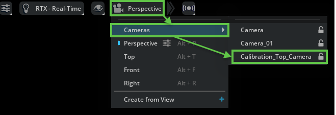
Switch the viewport to the new top view camera to verify that it covers the floorplan.
Tip
To switch the viewport to the top-view camera, click the Camera icon, then click Cameras > Calibration_Top_Camera.
Set Up the Calibration Tool Attributes#
This step is to enter the information needed for camera calibration.
Enter the place information in Place Info. In this case, it’s
city=Santa Clara/building=Isaac Sim Warehouse/room=Warehouse.Set Raycast Density, Minimum FOV Polygon Edge Length, and Minimum Area of FOV Polygon Hole to Ignore. See the Input Field for more details. In this case, use the default values.
Check the Create Camera View Images, Create FOV Polygon Images, and Show FOV Polygon boxes if these additional data are needed.
Set Output Folder Path by either entering the path or clicking the folder picker icon.
Generate Calibration Dots#
Generate calibration dots for each camera by clicking the Create Dot Prims button.
Note
Calibration dot prims are generated under
/World/Calibration_Dots/[Camera Name]/, where[Camera Name]is the name of the camera.For each camera prim under
/World/Cameras, six calibration dots are generated. The dot prims are used to calculate the projection matrix for each camera.You can switch your viewport to any camera’s view to check whether all calibration dots are visible.
Generate the Calibration File#
Generate the calibration file by clicking on the Generate Calibration File button. This generates a
calibration.jsonfile to Output Folder Path.After the
calibration.jsonfile is generated. You can visualize the FOV in the stage by selecting the target camera.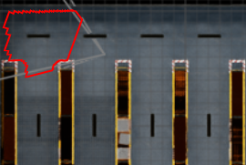
Note
Your result might look different because it depends on the camera parameters. In this tutorial, the translate of the camera is (-13.02311, 7.20828, 5.0), the orient is (-55.253, -56.035, -150.088), and the camera focal length is 20.94.
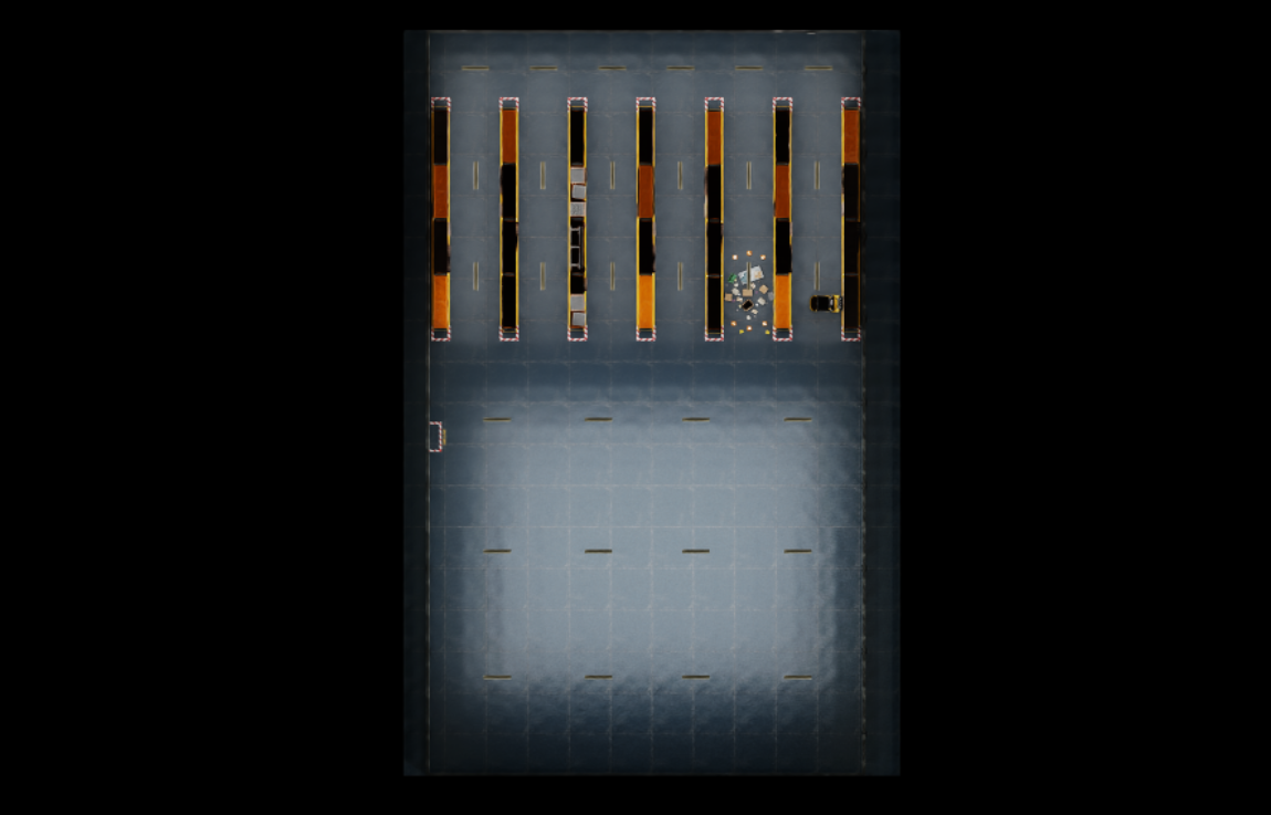
Generate Top View Image#
To visualize the generated FOV polygon top view image, generate the image by clicking on Generate Top View Image button.
The Top View Camera’s view will be rendered and output to the
[Output Folder Path]. AnimageMetadata.jsonfile is also generated to store image metadata.
Note
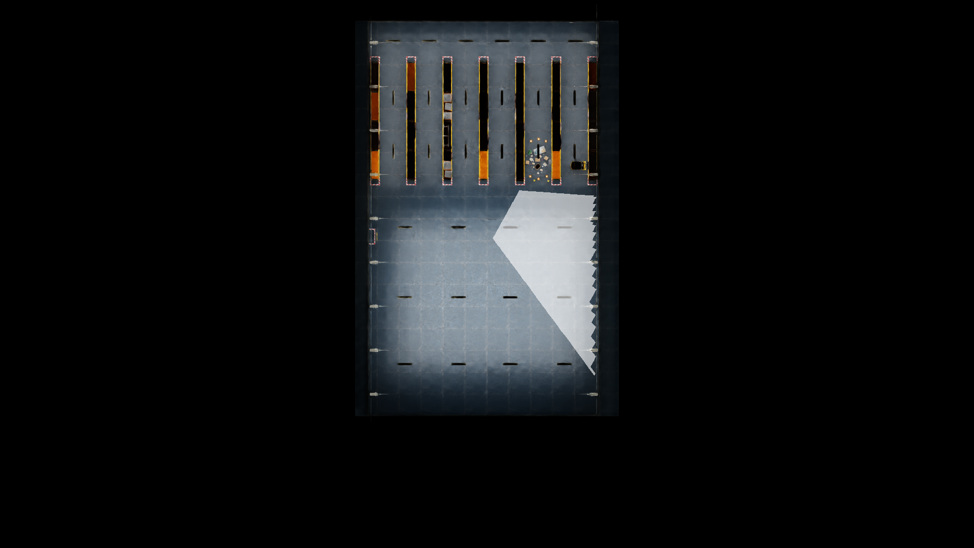
If Create FOV Polygon Images is checked, for each camera there will be an image with a white-shaded FOV polygon from the top view.
The FOV polygon images will be generated under [Output Folder Path]/Debug/fieldOfViewPolygon.