Tutorial 3: Inspect Asset#
You’ve seen how the Inspire Hand is built from multiple USD files (Tutorial 2). Next we inspect and validate that asset: joints, mass and inertia, and collision meshes. Skipping this step means you’re tuning in the dark—wrong masses or misaligned inertia can cause unstable or unrealistic motion even when joint parameters look correct, and the wrong collider type can slow the simulation or produce confusing contact behavior. Isaac Sim’s joint visualizer, Robot Inspector, Physics Debugger, and collider visualization give you a clear picture of the asset before you filter collision pairs or tune drives.
Learning Objectives#
In this tutorial, you will:
Enable the joint visualizer and interpret joint types.
Enable mass and inertia visualization.
Verify collision meshes and collider types.
Prerequisites#
Complete Tutorial 2: Asset Structure.
Have the Inspire Hand scene open in Isaac Sim with the PhysX variant selected.
Module 2.1: Enable Joint Visualizer#
Because we’re tuning for the PhysX backend, load the hand with the PhysX variant. Then enable joint visualization to see joint locations and types at a glance.
Viewport Navigation in Isaac Sim
Orbit the camera: Hold Alt and left mouse button, then drag.
Rotate in place (look around): Hold right mouse button and move the mouse.
Zoom: Hold Alt and right mouse button (or use the scroll wheel).
Pan: Hold the middle mouse button and drag.
Focus the camera on a prim: Select the desired prim in the Stage panel, then press F.
Use these controls to efficiently explore and inspect the Inspire Hand model as you follow the instructions below.
Open
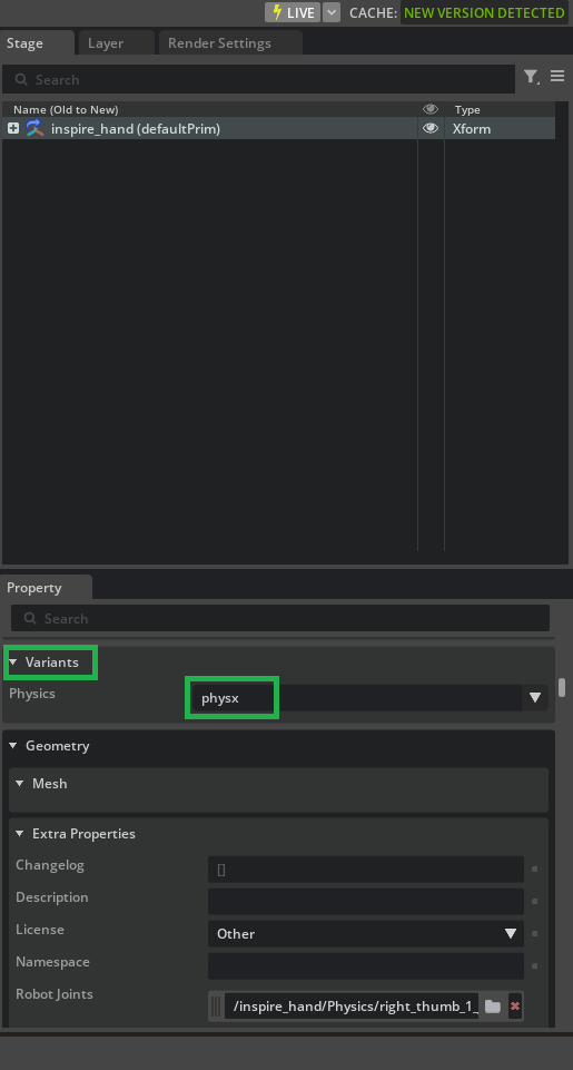
/path/to/Inspire/module_1_start/inspire_hand.usdain Isaac Sim.Select the top-level
inspire_handprim.In the Property panel, scroll to Variants and select PhysX.
Go to Eye > Show by Type > Physics > Joints to enable joint visualization.
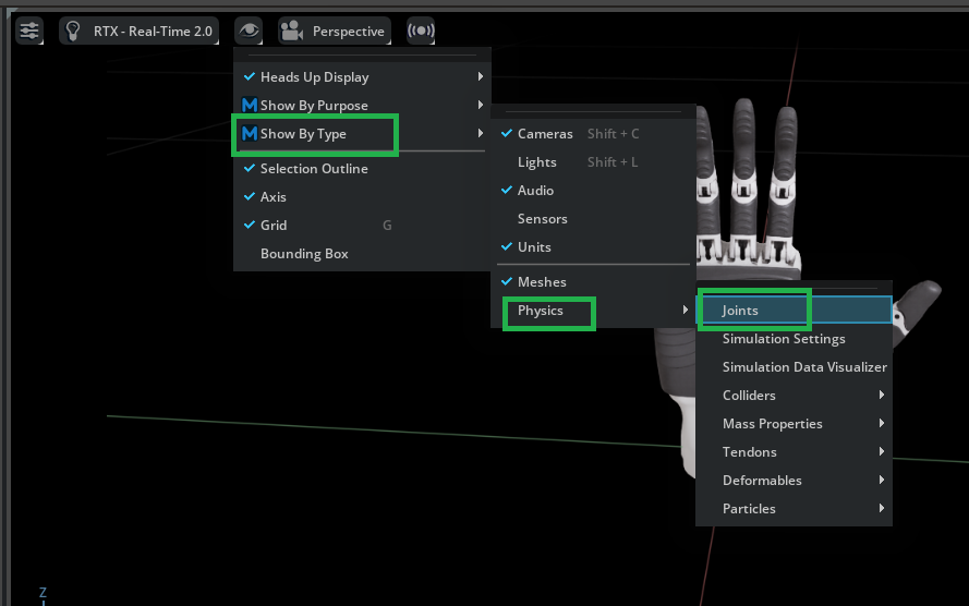
In the viewport, the Inspire Hand should now have gizmos identifying the locations and types of each joint.
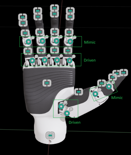
Examine the joints — In the Stage panel, under the /Physics scope, find right_index_1_joint—a Revolute joint responsible for the base motion of the index finger, represented by a circular icon in the viewport. Also locate right_index_rubber_1_joint, which is a Fixed joint attaching the lower index rubber pad to its link, shown as a rectangular icon in the visualization. The right_index_2_joint is a mimic joint that references the movement of right_index_1_joint (we’ll cover mimic joints in more detail in Tutorial 5). Understanding how these joints function and their naming conventions will be valuable when tuning the drives in Tutorials 5 and 6.
Module 2.2: Robot Inspector (hierarchy and session masking)#
With joint gizmos visible in the viewport, the Robot Inspector Window gives you the same articulation as a structured link → joint tree—often easier to scan than hunting only under /Physics when payloads and scopes spread prims across layers.
Open Window > Robot Inspector. The window docks next to Stage by default.
In the robot list, select the entry for the Inspire Hand.
Set the hierarchy mode to Tree (default): parent link → joint → child link.
Optionally switch to Flat (all links, then all joints) or MuJoCo (base-rooted body tree) to compare layouts; the same underlying articulation can be shown in three different ways.

The Deactivate, Bypass, and Anchor columns apply transient opinions on a dedicated session sublayer—they are not saved to your USD files. That is useful for quick isolation during debugging.
See also
Icons and behavior for Deactivate, Bypass, and Anchor are documented under Component Masking.
When Robot Inspector is open, joint connection lines (parent to child, with direction cues) will appear in the viewport when the Eye Icon > Show by Type > Physics > Joints is enabled; they are hidden during simulation playback as described in Robot Inspector Window.
Module 2.3: Verify Mass and Inertia Properties#
Mass and inertia define how each link responds to forces. If the principal inertia axes are misaligned with the link geometry, or if mass values are too small or too large, the hand can behave unrealistically. The Physics Debugger lets you visualize body axes and Body Mass Axes (principal inertia) so you can spot problems before running the simulation.
Open Utilities > Physics Debugger. The Physics Debug panel appears.

In Simulation Debug Visualization:
Check Enabled.
Check Body Axes to show coordinate frames.
Check Body Mass Axes to show principal inertia axes.
In Simulation Control, click Step to run one simulation frame and display the visualization.
Warning
Avoid pressing Play at this stage, as it may cause Isaac Sim to crash. Instead, use Simulation Control to either Run the physics simulation or Step through it one frame at a time.

For each link, you can now verify:
Mass centers sit appropriately within the link.
Principal inertia axes align with the link geometry.
Inertia values look plausible (not excessively small or large).
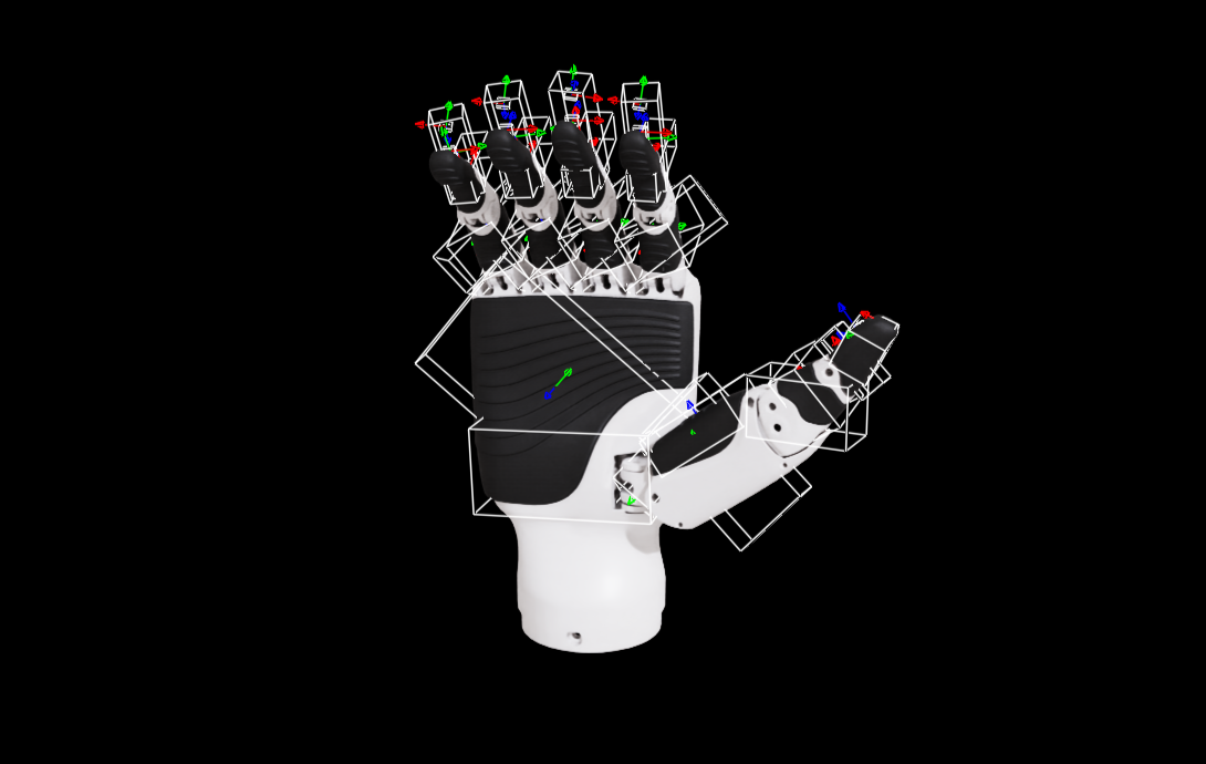
Note
Misaligned principal inertia axes can cause unstable or unrealistic motion. The image below shows an example of misalignment.
Alternative Method: Inspecting Mass and Inertia via the Physics Toolbar#
You can also inspect mass and inertia properties using the Physics Toolbar:
Go to Tools > Physics Toolbar.
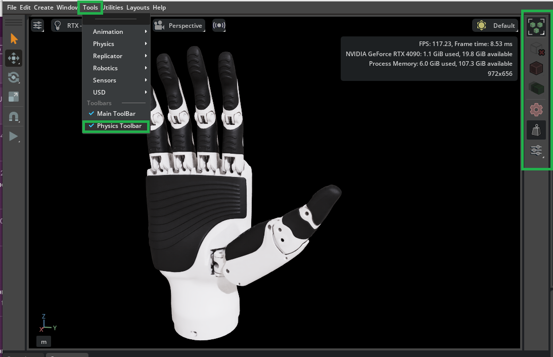
In the toolbar, toggle on both the Rigid Body Selection Mode (cube icon) and the Mass Distribution Manipulator (balance icon).
In the viewport, select any rigid body prim on the hand. The Mass Properties Info will be displayed, providing details about the total mass, center of mass, principal axis, and diagonal inertia directly in the viewport.

This method lets you quickly inspect and debug mass distribution for any body in the scene without navigating to the Property panel.
Module 2.4: Verify Collision Meshes#
The shapes you see in the viewport aren’t necessarily what the physics engine uses for contact—that’s determined by the collision meshes (colliders). Before we filter collision pairs in Tutorial 4, we inspect and verify the colliders: colliders are color-coded green for rigid bodies and magenta for static bodies.
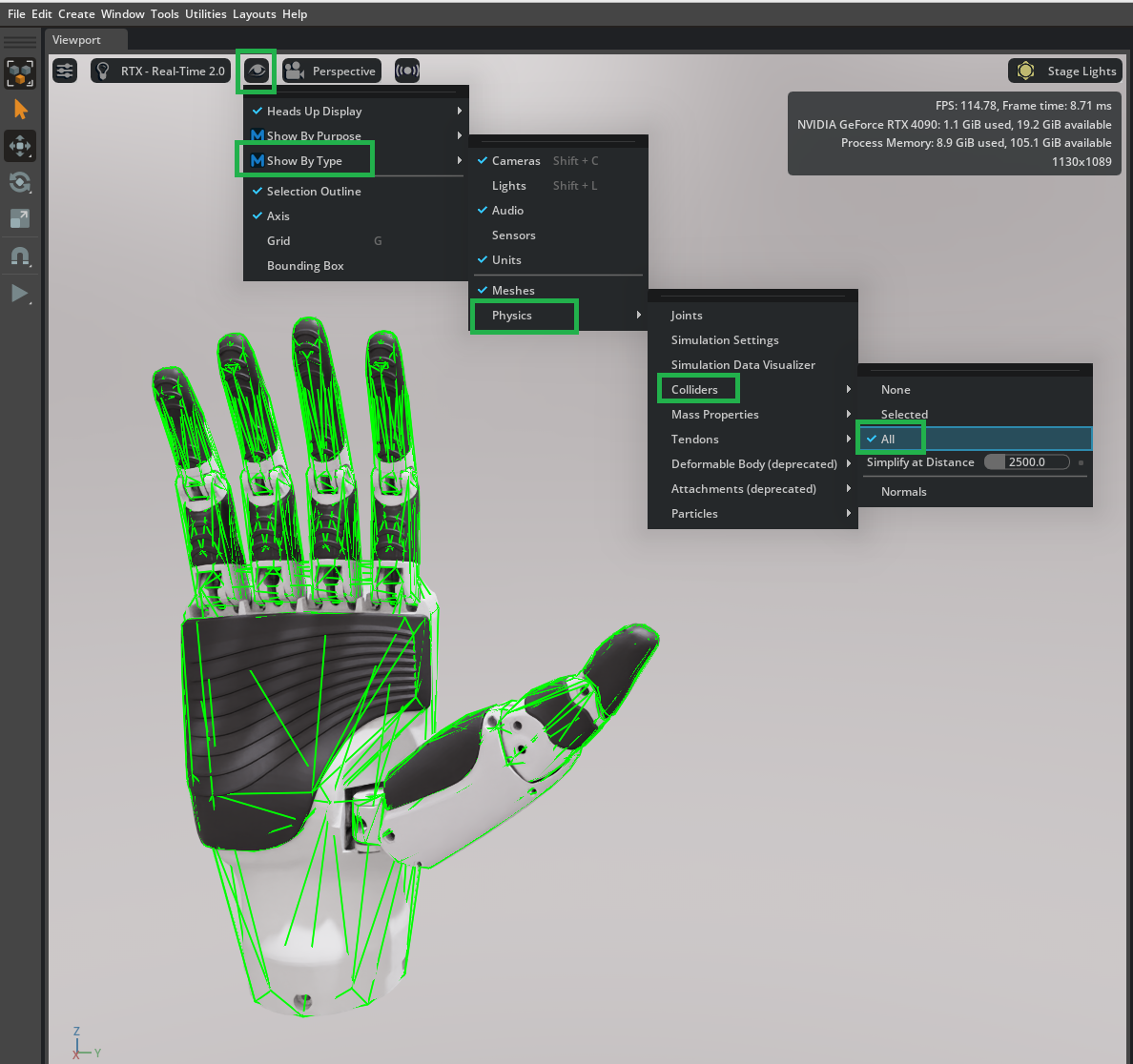
Go to Eye > Show by Type > Physics > Colliders > All to visualize all collision shapes.
Setting collider types affects performance and fidelity. You can mix types on one asset. For dexterous hands, Convex Hull is often used for parts that do not need high accuracy (e.g. palm), and Convex Decomposition for parts that need accurate contact (e.g. fingertips). Convex Decomposition gives the best shapes but costs more than Convex Hull or geometry-based colliders. In this tutorial we use Convex Hull for all parts.
Summary#
This tutorial covered:
Enabling the joint visualizer and identifying joint types (Fixed, Revolute, Mimic) in the Stage—the same structure you’ll tune in Tutorials 5 and 6.
Opening Robot Inspector to review the hand’s kinematic hierarchy (Flat / Tree / MuJoCo modes) and understanding session masking.
Using the Physics Debugger to visualize body axes and principal inertia and verifying that mass centers and inertia alignment look correct for each link.
Turning on collider visualization and confirming the collider strategy (Convex Hull for this series), so you know what shapes will collide when self-collisions are enabled in Tutorial 4.
Next Steps#
Continue to Tutorial 4: Collider Pairs to work through self-collision pairs with the Robot Self-Collision Detector, inspect collision geometry with the Physics Debugger as needed, and add filtered pairs.