训练 Jetbot: 基准真相#
有了定义的环境,我们现在可以开始修改我们的观测和奖励,以训练一个策略来充当 Jetbot 的控制器。作为用户,我们希望能够指定 Jetbot 驾驶的期望方向,并使车轮转动,使机器人以尽可能快的速度驾驶在指定的方向上。我们如何使用强化学习(RL)来实现这一点?如果您想直接查看此场景的结果,请查看本教程存储库的 此分支!
扩展环境#
我们需要做的第一件事是为场景上的每个 Jetbot 创建设置指令的逻辑。每个指令将是一个单位向量,我们需要为场景上机器人的每个克隆都需要一个,这意味着一个形状为 [num_envs, 3] 的张量。尽管 Jetbot 只在二维平面中导航,但通过使用三维向量,我们可以利用 Isaac Lab 提供的所有数学工具。
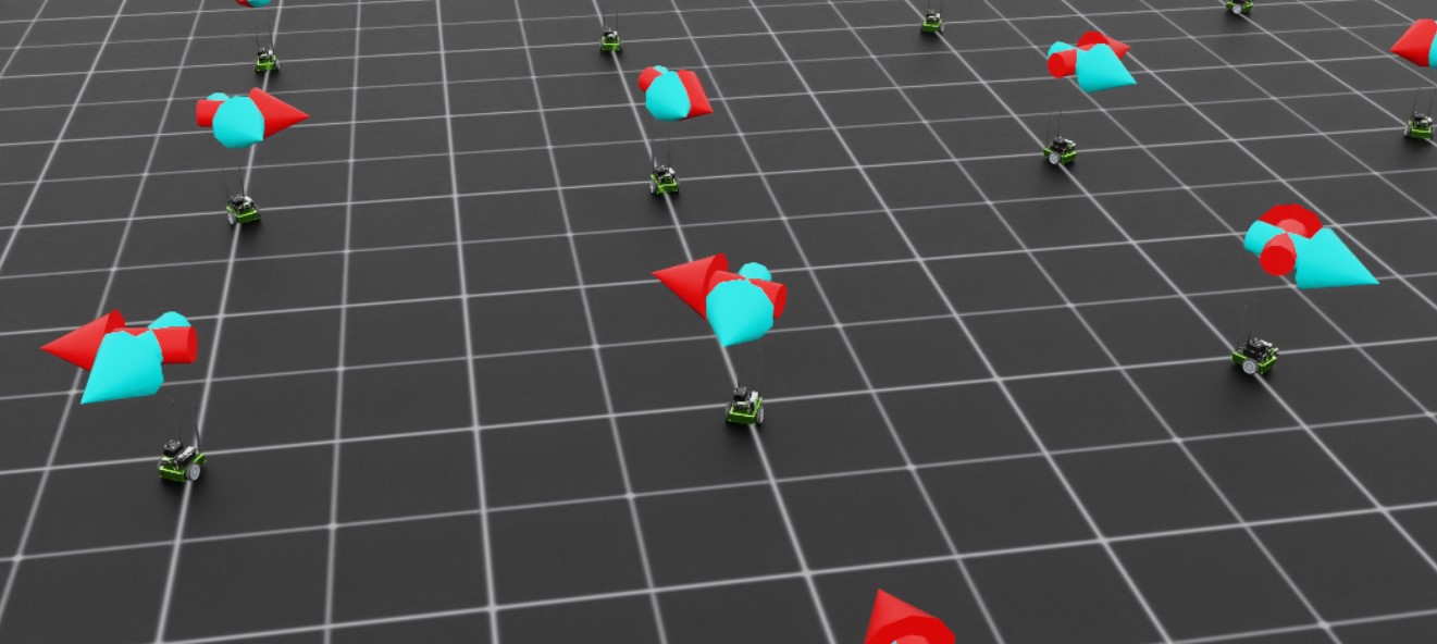
设置可视化也是一个好主意,这样我们在训练和推断过程中更容易了解策略的行为。在这种情况下,我们将定义两个箭头 VisualizationMarkers : 一个表示机器人的 "前进" 方向,另一个表示指令方向。当策略完全训练好时,这些箭头应该对齐!在早期设置这些可视化有助于我们避免 "潜在错误" : 代码中的问题不会导致崩溃。
首先,我们需要定义标志配置,然后使用该配置实例化标志。将以下内容添加到 isaac_lab_tutorial_env.py 的全局范围内
from isaaclab.markers import VisualizationMarkers, VisualizationMarkersCfg
from isaaclab.utils.assets import ISAAC_NUCLEUS_DIR
import isaaclab.utils.math as math_utils

def define_markers() -> VisualizationMarkers:
    """Define markers with various different shapes."""
    marker_cfg = VisualizationMarkersCfg(
        prim_path="/Visuals/myMarkers",
        markers={
                "forward": sim_utils.UsdFileCfg(
                    usd_path=f"{ISAAC_NUCLEUS_DIR}/Props/UIElements/arrow_x.usd",
                    scale=(0.25, 0.25, 0.5),
                    visual_material=sim_utils.PreviewSurfaceCfg(diffuse_color=(0.0, 1.0, 1.0)),
                ),
                "command": sim_utils.UsdFileCfg(
                    usd_path=f"{ISAAC_NUCLEUS_DIR}/Props/UIElements/arrow_x.usd",
                    scale=(0.25, 0.25, 0.5),
                    visual_material=sim_utils.PreviewSurfaceCfg(diffuse_color=(1.0, 0.0, 0.0)),
                ),
        },
    )
    return VisualizationMarkers(cfg=marker_cfg)
VisualizationMarkersCfg 定义 USD 原语来充当 "标志" 。 任何原语都可以,但通常您希望尽可能简化标志,因为在每个时间步骤运行时会对标志进行克隆。这是因为这些标志的目的仅用于 调试可视化 ,并不是仿真的一部分: 用户完全可以控制何时在何处绘制多少标志。NVIDIA在我们的公共nucleus服务器上提供了几个简单的网格,位于 ISAAC_NUCLEUS_DIR ,出于明显的原因,我们选择使用 arrow_x.usd 。
有关使用 VisualizationMarkers 的更详细示例,请查看 markers.py 演示!
markers.py 演示的代码
  1# Copyright (c) 2022-2026, The Isaac Lab Project Developers (https://github.com/isaac-sim/IsaacLab/blob/main/CONTRIBUTORS.md).
  2# All rights reserved.
  3#
  4# SPDX-License-Identifier: BSD-3-Clause
  5
  6"""This script demonstrates different types of markers.
  7
  8.. code-block:: bash
  9
 10    # Usage
 11    ./isaaclab.sh -p scripts/demos/markers.py
 12
 13"""
 14
 15"""Launch Isaac Sim Simulator first."""
 16
 17import argparse
 18
 19from isaaclab.app import AppLauncher
 20
 21# add argparse arguments
 22parser = argparse.ArgumentParser(description="This script demonstrates different types of markers.")
 23# append AppLauncher cli args
 24AppLauncher.add_app_launcher_args(parser)
 25# parse the arguments
 26args_cli = parser.parse_args()
 27
 28# launch omniverse app
 29app_launcher = AppLauncher(args_cli)
 30simulation_app = app_launcher.app
 31
 32"""Rest everything follows."""
 33
 34import torch
 35
 36import isaaclab.sim as sim_utils
 37from isaaclab.markers import VisualizationMarkers, VisualizationMarkersCfg
 38from isaaclab.sim import SimulationContext
 39from isaaclab.utils.assets import ISAAC_NUCLEUS_DIR, ISAACLAB_NUCLEUS_DIR
 40from isaaclab.utils.math import quat_from_angle_axis
 41
 42
 43def define_markers() -> VisualizationMarkers:
 44    """Define markers with various different shapes."""
 45    marker_cfg = VisualizationMarkersCfg(
 46        prim_path="/Visuals/myMarkers",
 47        markers={
 48            "frame": sim_utils.UsdFileCfg(
 49                usd_path=f"{ISAAC_NUCLEUS_DIR}/Props/UIElements/frame_prim.usd",
 50                scale=(0.5, 0.5, 0.5),
 51            ),
 52            "arrow_x": sim_utils.UsdFileCfg(
 53                usd_path=f"{ISAAC_NUCLEUS_DIR}/Props/UIElements/arrow_x.usd",
 54                scale=(1.0, 0.5, 0.5),
 55                visual_material=sim_utils.PreviewSurfaceCfg(diffuse_color=(0.0, 1.0, 1.0)),
 56            ),
 57            "cube": sim_utils.CuboidCfg(
 58                size=(1.0, 1.0, 1.0),
 59                visual_material=sim_utils.PreviewSurfaceCfg(diffuse_color=(1.0, 0.0, 0.0)),
 60            ),
 61            "sphere": sim_utils.SphereCfg(
 62                radius=0.5,
 63                visual_material=sim_utils.PreviewSurfaceCfg(diffuse_color=(0.0, 1.0, 0.0)),
 64            ),
 65            "cylinder": sim_utils.CylinderCfg(
 66                radius=0.5,
 67                height=1.0,
 68                visual_material=sim_utils.PreviewSurfaceCfg(diffuse_color=(0.0, 0.0, 1.0)),
 69            ),
 70            "cone": sim_utils.ConeCfg(
 71                radius=0.5,
 72                height=1.0,
 73                visual_material=sim_utils.PreviewSurfaceCfg(diffuse_color=(1.0, 1.0, 0.0)),
 74            ),
 75            "mesh": sim_utils.UsdFileCfg(
 76                usd_path=f"{ISAAC_NUCLEUS_DIR}/Props/Blocks/DexCube/dex_cube_instanceable.usd",
 77                scale=(10.0, 10.0, 10.0),
 78            ),
 79            "mesh_recolored": sim_utils.UsdFileCfg(
 80                usd_path=f"{ISAAC_NUCLEUS_DIR}/Props/Blocks/DexCube/dex_cube_instanceable.usd",
 81                scale=(10.0, 10.0, 10.0),
 82                visual_material=sim_utils.PreviewSurfaceCfg(diffuse_color=(1.0, 0.25, 0.0)),
 83            ),
 84            "robot_mesh": sim_utils.UsdFileCfg(
 85                usd_path=f"{ISAACLAB_NUCLEUS_DIR}/Robots/ANYbotics/ANYmal-C/anymal_c.usd",
 86                scale=(2.0, 2.0, 2.0),
 87                visual_material=sim_utils.GlassMdlCfg(glass_color=(0.0, 0.1, 0.0)),
 88            ),
 89        },
 90    )
 91    return VisualizationMarkers(marker_cfg)
 92
 93
 94def main():
 95    """Main function."""
 96    # Load kit helper
 97    sim_cfg = sim_utils.SimulationCfg(dt=0.01, device=args_cli.device)
 98    sim = SimulationContext(sim_cfg)
 99    # Set main camera
100    sim.set_camera_view([0.0, 18.0, 12.0], [0.0, 3.0, 0.0])
101
102    # Spawn things into stage
103    # Lights
104    cfg = sim_utils.DomeLightCfg(intensity=3000.0, color=(0.75, 0.75, 0.75))
105    cfg.func("/World/Light", cfg)
106
107    # create markers
108    my_visualizer = define_markers()
109
110    # define a grid of positions where the markers should be placed
111    num_markers_per_type = 5
112    grid_spacing = 2.0
113    # Calculate the half-width and half-height
114    half_width = (num_markers_per_type - 1) / 2.0
115    half_height = (my_visualizer.num_prototypes - 1) / 2.0
116    # Create the x and y ranges centered around the origin
117    x_range = torch.arange(-half_width * grid_spacing, (half_width + 1) * grid_spacing, grid_spacing)
118    y_range = torch.arange(-half_height * grid_spacing, (half_height + 1) * grid_spacing, grid_spacing)
119    # Create the grid
120    x_grid, y_grid = torch.meshgrid(x_range, y_range, indexing="ij")
121    x_grid = x_grid.reshape(-1)
122    y_grid = y_grid.reshape(-1)
123    z_grid = torch.zeros_like(x_grid)
124    # marker locations
125    marker_locations = torch.stack([x_grid, y_grid, z_grid], dim=1)
126    marker_indices = torch.arange(my_visualizer.num_prototypes).repeat(num_markers_per_type)
127
128    # Play the simulator
129    sim.reset()
130    # Now we are ready!
131    print("[INFO]: Setup complete...")
132
133    # Yaw angle
134    yaw = torch.zeros_like(marker_locations[:, 0])
135    # Simulate physics
136    while simulation_app.is_running():
137        # rotate the markers around the z-axis for visualization
138        marker_orientations = quat_from_angle_axis(yaw, torch.tensor([0.0, 0.0, 1.0]))
139        # visualize
140        my_visualizer.visualize(marker_locations, marker_orientations, marker_indices=marker_indices)
141        # roll corresponding indices to show how marker prototype can be changed
142        if yaw[0].item() % (0.5 * torch.pi) < 0.01:
143            marker_indices = torch.roll(marker_indices, 1)
144        # perform step
145        sim.step()
146        # increment yaw
147        yaw += 0.01
148
149
150if __name__ == "__main__":
151    # run the main function
152    main()
153    # close sim app
154    simulation_app.close()
接下来,我们需要扩展初始化和设置步骤,以构建我们需要用于跟踪命令以及标志位置和旋转的数据。将 _setup_scene 的内容替换为以下内容
def _setup_scene(self):
    self.robot = Articulation(self.cfg.robot_cfg)
    # add ground plane
    spawn_ground_plane(prim_path="/World/ground", cfg=GroundPlaneCfg())
    # clone and replicate
    self.scene.clone_environments(copy_from_source=False)
    # add articulation to scene
    self.scene.articulations["robot"] = self.robot
    # add lights
    light_cfg = sim_utils.DomeLightCfg(intensity=2000.0, color=(0.75, 0.75, 0.75))
    light_cfg.func("/World/Light", light_cfg)

    self.visualization_markers = define_markers()

    # setting aside useful variables for later
    self.up_dir = torch.tensor([0.0, 0.0, 1.0]).cuda()
    self.yaws = torch.zeros((self.cfg.scene.num_envs, 1)).cuda()
    self.commands = torch.randn((self.cfg.scene.num_envs, 3)).cuda()
    self.commands[:,-1] = 0.0
    self.commands = self.commands/torch.linalg.norm(self.commands, dim=1, keepdim=True)

    # offsets to account for atan range and keep things on [-pi, pi]
    ratio = self.commands[:,1]/(self.commands[:,0]+1E-8)
    gzero = torch.where(self.commands > 0, True, False)
    lzero = torch.where(self.commands < 0, True, False)
    plus = lzero[:,0]*gzero[:,1]
    minus = lzero[:,0]*lzero[:,1]
    offsets = torch.pi*plus - torch.pi*minus
    self.yaws = torch.atan(ratio).reshape(-1,1) + offsets.reshape(-1,1)

    self.marker_locations = torch.zeros((self.cfg.scene.num_envs, 3)).cuda()
    self.marker_offset = torch.zeros((self.cfg.scene.num_envs, 3)).cuda()
    self.marker_offset[:,-1] = 0.5
    self.forward_marker_orientations = torch.zeros((self.cfg.scene.num_envs, 4)).cuda()
    self.command_marker_orientations = torch.zeros((self.cfg.scene.num_envs, 4)).cuda()
大部分是为命令和标志设置记录,但命令初始化和航向计算值得深入研究。命令通过 torch.randn 从一个多变量正态分布采样,其中 z 分量固定为零,然后归一化为单位长度。为了让我们的命令标志沿着这些向量指向,我们需要适当旋转基本箭头网格。这意味着我们需要定义一个 四元数 ,这个四元数将使箭头原语绕 z 轴旋转一定角度。按照惯例,绕 z 轴的旋转称为 "yaw" 旋转(类似于roll和pitch)。
幸运的是,Isaac Lab 提供了一个从旋转轴和角度生成四元数的实用程序: isaaclab.utils.math.quat_from_axis_angle() ,现在唯一棘手的部分是确定那个角度。

yaw是围绕 z 轴定义的,yaw为 0 与 x 轴对齐,并且正角度逆时针打开。命令向量的 x 和 y 分量定义了这个角的切线,因此我们需要这个比率的 反正切 来获得yaw。
现在考虑两个命令: 命令 A 在第二象限处 (-x,y),而命令 B 在第四象限处 (x,-y)。对于 A 和 B,y 分量与 x 分量的比率是相同的。如果我们不考虑这一点,那么一些命令箭头将指向与命令相反的方向!本质上,我们的命令是定义在 [-pi, pi] 上的,但 反正切 仅在 [-pi/2, pi/2] 上定义。
为了纠正这一点,根据命令所在象限添加或减去 pi 来确定yaw。
ratio = self.commands[:,1]/(self.commands[:,0]+1E-8) #in case the x component is zero
gzero = torch.where(self.commands > 0, True, False)
lzero = torch.where(self.commands < 0, True, False)
plus = lzero[:,0]*gzero[:,1]
minus = lzero[:,0]*lzero[:,1]
offsets = torch.pi*plus - torch.pi*minus
self.yaws = torch.atan(ratio).reshape(-1,1) + offsets.reshape(-1,1)
涉及张量的布尔表达式可能具有模糊的定义,pytorch 将抛出与此相关的错误。 Pytorch 提供了各种方法使定义明确化。方法 torch.where 生成一个与输入形状相同的张量,输出的每个元素都是根据该元素的评估而确定的。处理张量的布尔运算的一个可靠方法是简单地生成布尔索引张量,然后用代数方式表示操作,将 AND 表示为乘法, OR 表示为加法,这就是我们在上面所做的。 这等同于伪代码:
yaws = torch.atan(ratio)
yaws[commands[:,0] < 0 and commands[:,1] > 0] += torch.pi
yaws[commands[:,0] < 0 and commands[:,1] < 0] -= torch.pi
接下来是实际可视化标志的方法。记住,这些标志不是场景实体!我们需要在想看到它们时 "绘制" 它们。
def _visualize_markers(self):
    # get marker locations and orientations
    self.marker_locations = self.robot.data.root_pos_w
    self.forward_marker_orientations = self.robot.data.root_quat_w
    self.command_marker_orientations = math_utils.quat_from_angle_axis(self.yaws, self.up_dir).squeeze()

    # offset markers so they are above the jetbot
    loc = self.marker_locations + self.marker_offset
    loc = torch.vstack((loc, loc))
    rots = torch.vstack((self.forward_marker_orientations, self.command_marker_orientations))

    # render the markers
    all_envs = torch.arange(self.cfg.scene.num_envs)
    indices = torch.hstack((torch.zeros_like(all_envs), torch.ones_like(all_envs)))
    self.visualization_markers.visualize(loc, rots, marker_indices=indices)
VisualizationMarkers 的 visualize 方法类似于这个 "draw" 函数。它接受用于标志的空间变换的张量,以及一个 marker_indices 张量,用于指定每个标志原型用于每个标志。 只要所有这些张量的第一个维度匹配,此函数将使用指定的转换绘制这些标志。 这就是我们堆叠位置、旋转和索引的原因。
现在,我们只需要在预物理步骤上调用 _visualize_markers 来使箭头可见。将 _pre_physics_step 替换为以下内容
def _pre_physics_step(self, actions: torch.Tensor) -> None:
  self.actions = actions.clone()
  self._visualize_markers()
进入 RL 训练之前的最后一项主要修改是更新 _reset_idx 方法以考虑命令和标志。每当重置环境时,我们都需要生成一个新的命令并重置标志。 这方面的逻辑已经在上面讨论过。将 _reset_idx 的内容替换为以下内容:
def _reset_idx(self, env_ids: Sequence[int] | None):
    if env_ids is None:
        env_ids = self.robot._ALL_INDICES
    super()._reset_idx(env_ids)

    # pick new commands for reset envs
    self.commands[env_ids] = torch.randn((len(env_ids), 3)).cuda()
    self.commands[env_ids,-1] = 0.0
    self.commands[env_ids] = self.commands[env_ids]/torch.linalg.norm(self.commands[env_ids], dim=1, keepdim=True)

    # recalculate the orientations for the command markers with the new commands
    ratio = self.commands[env_ids][:,1]/(self.commands[env_ids][:,0]+1E-8)
    gzero = torch.where(self.commands[env_ids] > 0, True, False)
    lzero = torch.where(self.commands[env_ids]< 0, True, False)
    plus = lzero[:,0]*gzero[:,1]
    minus = lzero[:,0]*lzero[:,1]
    offsets = torch.pi*plus - torch.pi*minus
    self.yaws[env_ids] = torch.atan(ratio).reshape(-1,1) + offsets.reshape(-1,1)

    # set the root state for the reset envs
    default_root_state = self.robot.data.default_root_state[env_ids]
    default_root_state[:, :3] += self.scene.env_origins[env_ids]

    self.robot.write_root_state_to_sim(default_root_state, env_ids)
    self._visualize_markers()
就是这样!我们现在生成命令并可以可视化 Jetbot 的航向了。我们准备开始调整观测和奖励。