Data Generation with MobilityGen#
MobilityGen is a toolset built on NVIDIA Isaac Sim that enables you to generate and collect data for mobile robots.

MobilityGen supports:
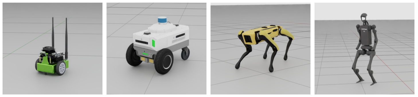
- Many robot types
Differential drive - Jetbot, Carter
Quadruped - Spot
Humanoid - H1
- Many sensor configurations
- Single front-camera configurations
JetbotRobot, CarterRobot, H1Robot, SpotRobot
- USD-based multi-sensor rigs (current version supports multi-camera only)
JetbotMultiSensorRobot, CarterMultiSensorRobot, H1MultiSensorRobot, SpotMultiSensorRobot
- Many data collection methods
Manual - Keyboard Teleoperation, Gamepad Teleoperation
Automated - Random Accelerations, Random Path Following
Generate Data with MobilityGen#
Launch Isaac Sim#
Open Isaac Sim from the terminal with multi-GPU rendering disabled:
./isaac-sim.sh --/renderer/multiGpu/enabled=false
Note
Always launch Isaac Sim with --/renderer/multiGpu/enabled=false when using
MobilityGen. On machines with multiple GPUs, leaving multi-GPU rendering enabled
can cause CUDA errors or crashes during MobilityGen startup.
Build an Occupancy Map#
You must create an occupancy map of your environment.
This tutorial uses an example warehouse scene.
Load the warehouse stage:
Open Content Browser if it’s not already open (Window > Browsers > Content).
Load the warehouse USD file in Isaac Sim/Environments/Simple_Warehouse/warehouse_multiple_shelves.usd.
Create the occupancy map:
Select Tools > Robotics > Occupancy Map to open the Occupancy Map extension.
In the Occupancy Map window set Origin to:
X:2.0Y:0.0Z:0.0
To input a value in the text box,
ctrl + left clickto activate the input mode.In the Occupancy Map window set Upper Bound to:
X:10.0Y:20.0Z:2.0(Assumes the robot can move under two meter overpasses)
In the Occupancy Map window set Lower Bound to:
X:-14.0Y:-18.0Z:0.1(Assume the robot can move over5cmbumps)
Please note, the coordinates specified for the occupancy upper and lower bound define a bounding box within the warehouse_multiple_shelves.usd scene that we want the robot to be able to navigate. We’ve pre-selected values that cover the main floor area. When using a different scene, you may adjust these bounds to cover the area suitable for your USD scene.
Click Calculate to generate the occupancy map.
Click Visualize Image to view the occupancy map.
Enter “map” in the Image File Name field and click Update YAML.
Click Save YAML.
In the tree explorer, open the folder
~/MobilityGenData/maps/warehouse_multiple_shelves.On Windows replace ~ with the directory of your choice.
Under the file name enter
map.yamland click save.Back in the Visualization window, click Save Image.
In the tree explorer, open the folder
~/MobilityGenData/maps/warehouse_multiple_shelves.Under the file name enter
map.pngand click save.
Verify that you now have a folder named ~/MobilityGenData/maps/warehouse_multiple_shelves/ with
a file named map.yaml and map.png inside.
Record a Trajectory#
After creating a map of the environment, you can generate data with MobilityGen:
Enable the MobilityGen UI extension.
Navigate to Window > Extensions and search for MobilityGen UI.
Click the toggle switch for the MobilityGen UI extension.
Verify that two windows open. One window is the MobilityGen UI, the other is to display the Occupancy Map and visualizations. One window might be hiding behind the other when they first appear, so we recommend dragging them into a window pane to view both at the same time.
Build the scenario:
In the MobilityGen window under Stage paste the following USD:
In the MobilityGen window under Occupancy Map enter the path to the
map.yamlfile created previously.~/MobilityGenData/maps/warehouse_multiple_shelves/map.yaml
Under the Robot dropdown select H1Robot.
Under the Scenario dropdown select KeyboardTeleoperationScenario.
Click Build.
After a few seconds, verify that the scene and occupancy map appear.

Test drive the robot using the following keys:
W- Move forwardA- Turn leftS- Move backwardsD- Turn right
Start recording:
Click Start recording to start recording a log.
Move the robot around.
Click Stop recording to stop recording.

The data is now recorded to ~/MobilityGenData/recordings by default.
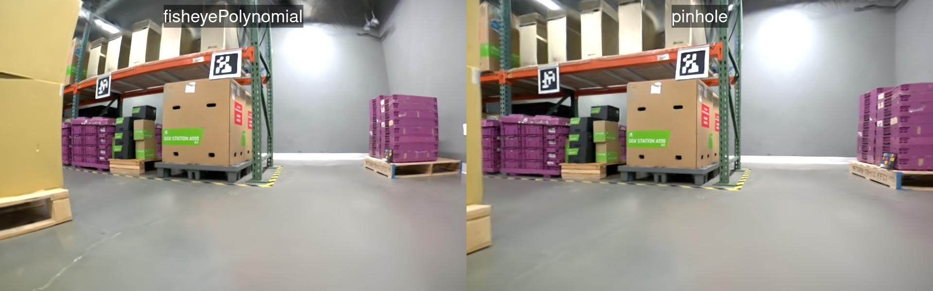
Sensor calibration overrides#
If you change sensors on the robot in Isaac Sim—for example camera intrinsics, distortion coefficients, projection type, or sensor transforms—MobilityGen persists those edits as a small USD diff, not a full copy of the robot asset.
The comparison below contrasts replay without the persisted override file against replay with
sensor_overrides.usda applied, so rendered cameras match the calibration from capture time.
The following screen capture walks through applying sensor calibration in the UI and how that ties
into recording and replay with sensor_overrides.usda.

The MobilityGen extension uses the helpers in
source/extensions/isaacsim.replicator.experimental.mobility_gen/python/impl/sensor_overrides.py
to:
Save calibration overrides from the live stage into a file named
sensor_overrides.usdainside each recording directory. Only attributes you changed (relative to the referenced robot USD) are written; the result is a lightweight override layer.Apply that same file when you replay or render: the extension loads
sensor_overrides.usdaand merges those opinions onto the robot prim subtree so nested cameras and rigs match the calibration from capture time.
sensor_overrides.usda is optional: if a recording does not contain one (for example,
recordings predating this feature), no overrides are applied during replay.
Replay and Render#
After recording a trajectory (robot poses and joint state), you can replay it headlessly to render sensor images (RGB, depth, segmentation, normals) without re-running the physics simulation.
Note
Recordings made with Isaac Sim 5.x use a different on-disk format than 6.0 and must be converted before replay. See MobilityGen Recordings for the conversion script.
Isaac Sim ships a standalone replay script for this. Run it from the Isaac Sim root directory
(replace ~/omni_isaac_sim with your actual Isaac Sim installation path):
./python.sh \
    standalone_examples/replicator/mobility_gen/replay_directory.py \
    --input  ~/MobilityGenData/recordings \
    --output ~/MobilityGenData/replays \
    --render_interval 40
--input— directory containing one or more recordings (each in its own subdirectory).--output— directory where replays with rendered sensor data will be written.--render_interval— render every Nth physics step.40renders roughly once per second and is a good starting point; set to1for full-frame-rate output.
Additional optional flags:
--rgb_enabled— enable RGB image rendering (default:True).--depth_enabled— enable depth image rendering (default:True).--segmentation_enabled— enable semantic segmentation rendering (default:True).--normals_enabled— enable surface normal rendering (default:False).--instance_id_segmentation_enabled— enable instance segmentation rendering (default:False).--render_rt_subframes— number of RT subframes per step; increase for higher rendering quality at the cost of speed (default:1).
After the script finishes, verify that you have a folder ~/MobilityGenData/replays, which contains
the rendered sensor data.
You can open this folder to explore the data. Some data (like segmentation masks) can be difficult to visualize using the file browser alone.
Fortunately, there are many examples on how to load and work with the recorded data in the open source MobilityGen GitHub Repository. We recommend visualizing your recorded data by running the Gradio Visualization Script.
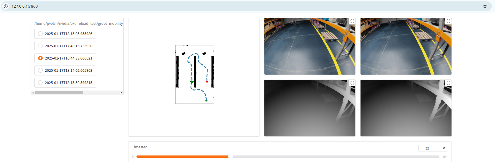
To run this example you would clone the above repository and run the following command from a Python interpreter with Gradio installed
python examples/04_visualize_gradio.py --input_dir ~/MobilityGenData/replays
You can also check the reader.py file for a helper class for reading the data in Python.
Tips#
Generate Procedural Data#
Generating procedural mobility data with MobilityGen is done very similar to the basic teleoperation workflow above.
To generate procedural data:
Follow
Build an Occupancy Mapabove to create an occupancy map of the environment.Follow
Record a Trajectoryabove, but selectRandomPathFollowingScenarioinstead ofKeyboardTeleoperationScenario. - You no longer need to manually teleoperate the robot. When the scenario is built, it will run and reset automatically. - You do need to hit “start recording” to enable recording to disk. However, when the scenario resets, a new recording will be created automatically. - Verify that you have recordings collected in the~/MobilityGenDatafolder the same as above.Follow
Replay and renderabove to render the sensor data from the recorded trajectories.
The process for other procedural scenarios (like RandomAccelerationScenario) is similar.
Add a Custom Robot#
You can implement a new robot for use with MobilityGen. This involves editing the robots.py file in the MobilityGen Examples extension.
The general workflow is as follows:
Open the
robots.pyfile in an editor of choice. This is located at<isaac sim path>/exts/isaacsim.replicator.mobility_gen.examples/isaacsim/replicator/mobility_gen/examples/robots.py.Create a new class that subclasses the
MobilityGenRobotclass. Alternatively, if your robot fits one of the existing implementations (likeWheeledMobilityGenRobot), you can subclass that.We recommend starting by reviewing an existing robot implementation in
robots.py, to get started. A good way to start is by customizing an existing robot.
If you are starting from scratch, implement the required abstract methods of
MobilityGenRobotclass:Implement the
build()method. This method is responsible for adding the robot to the USD stage.Implement the
write_action()method. This method takes as input a linear and angular velocity command and performs any control logic.Overwrite common class parameters (like physics_dt).
Register the robot class by using the
ROBOTS.register()decorator. This makes the custom robot discoverable by MobilityGen.
After implementing this in the file above, save the file.
When you restart Isaac Sim, verify that the new robot is registered, in the MobilityGen UI, and ready for data collection.
Because the registration of a new robot requires editing the Isaac Sim build file, make a copy of your robot.py externally so you do not lose it.
When defining your robot, you may find the following list of common parameters and their descriptions helpful
Parameter |
Description |
|---|---|
|
The physics timestep to use for simulating the robot. |
|
The Z-axis offset height to spawn the robot. |
|
The relative USD path which will be used to spawn the third person view camera. This is typically set to the robot base frame. |
|
The relative X-axis offset to spawn the third person view camera. |
|
The relative Z-axis offset to spawn the third person view camera. |
|
The tilt angle to apply to the third person view camera. |
|
The robot footprint radius to use for spawning and path planning. |
|
The robot footprint radius to use for collision based episode termination. |
|
The static class representing the front camera. |
|
The relative USD path to spawn the front camera. |
|
The relative XYZ rotation used when spawning the front camera. |
|
The relative XYZ translation used when spawning the front camera. |
|
The gain used to map keyboard button presses to the robot’s linear velocity. A larger gain results in faster movement. |
|
The gain used to map keyboard button presses to the robot’s angular velocity. A larger gain results in faster movement. |
|
The gain used to map gamepad axis movement to the robot’s linear velocity. A larger gain results in faster movement. |
|
The gain used to map gamepad axis movement to the robot’s angular velocity. A larger gain results in faster movement. |
|
The robot linear velocity limits for the random acceleration scenario. |
|
The robot angular velocity limits for the random acceleration scenario. |
|
The standard deviation used for sampling the robot linear acceleration each timestep during the random acceleration scenario. |
|
The standard deviation used for sampling the robot angular acceleration each timestep during the random acceleration scenario. |
|
The grid size to use for spawning the robot during the random acceleration scenario. |
|
The constant linear speed to use for the path following scenario. |
|
The gain used for the proportional steering control in the path following scenario. A larger gain results in quicker turning, but potential overshoot and wobbling. |
|
The distance threshold at which point the robot will stop. Applies to the path following scenario. |
|
The angle threshold at which point the robot will move forward. Applies to the path following scenario. |
|
The offset distance used to generate the ‘target point’ that the robot will follow in the path following scenario. A larger offset results in smoother motion, but too large may cause the robot to cut corners during turns. |
Use NuRec Assets in MobilityGen#
MobilityGen operates on USD environments, including 3D reconstructed scenes produced with the NVIDIA NuRec pipeline. The NVIDIA PhysicalAI-Robotics NuRec dataset provides ready-to-use indoor scenes that can be used directly as MobilityGen stages.
Overview#
NuRec scenes are published in two USD formats: Particle USD, a particle-based representation, and Volume USD, a volumetric representation. Either format can be used as the MobilityGen stage, and many scenes also include a pre-computed occupancy map that can replace manual map generation.
This workflow follows the same core MobilityGen pipeline described above: select or generate an occupancy map, record a trajectory, and replay that trajectory to render sensor data. Only the source of the stage and occupancy map changes when working with NuRec assets.

Use a NuRec Scene#
Download a scene USD file in either particle or volume format from the NVIDIA PhysicalAI-Robotics NuRec dataset.
If the dataset provides an occupancy map for the selected scene, use that file directly and skip occupancy-map generation.
If no occupancy map is available, load the reconstructed USD in Isaac Sim and follow the same occupancy-map procedure used for other MobilityGen environments.
In the MobilityGen window, set Stage to the path of the NuRec scene USD, for example:
/path/to/nurec_scene.usd
Set Occupancy Map to the corresponding
map.yamlfile, either from the dataset or from the generated output.Continue with the standard MobilityGen flow: record a trajectory, then run
replay_directory.pyto replay and render sensor data.
Note
RGB rendering is fully supported for trajectories recorded in reconstructed environments. Depth rendering can be enabled, but accuracy is not guaranteed because reconstructed geometry may be incomplete or noisy. Semantic segmentation is not supported for reconstructed scenes in this workflow.
To skip depth and semantic segmentation during replay (recommended for NuRec-only workflows),
pass the negated flags supported by replay_directory.py:
./python.sh \
    standalone_examples/replicator/mobility_gen/replay_directory.py \
    --input  ~/MobilityGenData/recordings \
    --output ~/MobilityGenData/replays \
    --render_interval 6 \
    --no-depth_enabled \
    --no-segmentation_enabled
--no-depth_enabled turns off depth image rendering; --no-segmentation_enabled turns off
semantic segmentation. RGB remains on by default (use --no-rgb_enabled only if you want to
disable RGB as well).
Occupancy-map quality depends on the collision geometry available in the USD stage. When generating a map for a reconstructed scene, review the occupancy-map visualization and adjust bounds as needed before recording trajectories.
Next Steps#
In this tutorial, you:
Built an occupancy map for use with MobilityGen.
Recorded a MobilityGen trajectory using the H1 robot with keyboard Teleoperation.
Rendered sensor data based on the recorded trajectory.
As next steps, try recording data:
for a different robot (for example: Spot)
using a different scenario (for example: Random Path Following)