Tutorial 4: Collider Pairs#
We inspected the asset structure and collision meshes. Now we tackle a question that makes or breaks this dexterous hand simulation: which parts of the hand are allowed to collide with each other? In the real world, a finger can’t pass through the palm, but in simulation, overlapping collision geometry between links can create phantom contacts, jitter, and forces that blow the hand apart. Filtered Pairs in Isaac Sim let you turn off collision between specific rigid bodies so you keep the contacts that matter (finger on object, intentional finger-to-finger) and remove the ones that cause instability.
Learning Objectives#
In this tutorial, you will:
Explain how Filtered Pairs work and when to use them.
Identify overlapping self-collision pairs with the Robot Self-Collision Detector and inspect collision geometry with the Physics Debugger as needed.
Add filtered pairs for the palm and pinky using Filtered Pair in the detector or Filtered Pairs on the Property panel, on the physics.usda layer.
Prerequisites#
Complete Tutorial 3: Inspect Asset.
Have the Inspire Hand scene open in Isaac Sim with joint and collider visualization familiar from the previous tutorial.
Module 3.1: Understanding Filtered Pairs#
Filtered Pairs explicitly tell the physics engine: “Do not detect collision between these two rigid bodies.” In Isaac Sim, adjacent links (two links connected by a joint) in an articulation don’t self-collide by default, but non-adjacent links do. As you will see, many of those non-adjacent links can have overlapping or very close collision geometry. In these scenarios, you can get:
Unrealistic forces — The solver tries to resolve interpenetration between links that would never actually touch in the real mechanism.
Instability — The hand can jitter, jump, or blow apart as conflicting contacts fight each other.
Wasted compute — Simulating every anatomically possible self-contact is rarely necessary for grasping or manipulation.
So the goal is to filter the problematic pairs while keeping contacts that you care about (e.g. finger–object, or specific finger–finger contacts). Use filtered pairs judiciously: over-filtering can allow unrealistic interpenetration; under-filtering can cause instability. We’ll turn on self-collisions, run the Robot Self-Collision Detector to see which links overlap at rest, then author filters on physics.usda. The Physics Debugger is also available to view solid collision meshes in the viewport while you reason about a pair.
Module 3.2: Enable self-collision and inspect pairs#
Which pairs should you filter? At the current configuration, the self-collision detector queries the physics engine for overlapping colliders, maps them to rigid-body links, and shows them in a sortable, searchable table.
Note
For this tutorial we focus on the pinky (little finger) as a clear example; the same workflow applies to other fingers or links.
Step 1: Reproduce the problem#
Press Play. With self-collisions disabled, the simulation is stable. Press Stop.
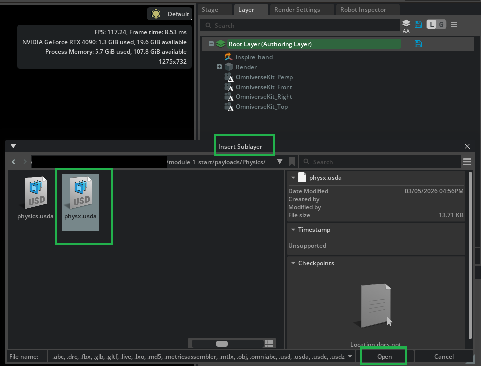
Because enabling Articulation Root is a PhysX-specific API, we want to make sure we are authoring on the physx.usda layer. In the Layer tab, click the Insert Sublayer icon to add a new sublayer beneath the current layer stack.
In the file dialog, navigate to
/path/to/Inspire/module_1_start/payloads/Physics/, selectphysx.usda, and click Open to insert it as a sublayer.
Once physx.usda appears in the layer stack, Right-click on physx.usda and select Set Authoring Layer.

You should now see the physx.usda layer highlighted green, indicating it is the active authoring layer.

In the Stage panel, select
r_base_link. In the Property panel, scroll to Articulation Root and check Self Collisions Enabled.
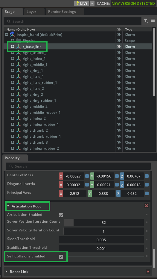
Press Play again. Links move erratically as overlapping collision geometry between non-adjacent links is now colliding, and the solver can’t resolve it cleanly.
Step 2: Run the Robot Self-Collision Detector#
With Self Collisions Enabled on the articulation root, the physics engine can evaluate which collider pairs overlap in the hand’s current configuration. The detector surfaces those pairs in a docked panel so you can inspect them and conveniently toggle Filtered Pair.
Note
If Self Collisions on the articulation root are disabled, the tool reports no overlapping pairs from the collision engine—see User Interface. Keep self-collisions on for this tutorial.
Press Stop if the simulation is still running so the hand returns to a stable pose for analysis.
Open Tools > Robotics > Asset Editors > Robot Self-Collision Detector.
In the Robot dropdown, select the Inspire Hand.
Leave Include environment collisions off unless you have added props; we only need self-pairs for this exercise.
Click Check Collisions. The table fills with Rigid Body A and Rigid Body B for each overlapping pair.

Use the search field or column sort to find rows that involve the pinky and palm—for example pairs that include
r_base_linkwithright_little_rubber_1, andright_little_1withright_little_rubber_2. You will enable Filtered Pair on those rows in the next module.Click a row to highlight both bodies in the viewport with distinct outline colors so you can confirm which links the table refers to.

Use the focal (crosshair) icons next to a body name to select that body’s collision prims in the Stage when you need a closer look.
Sorting, batch checkbox toggles, multi-row selection, and keyboard navigation are described in Robot Self-Collision Detector.
Solid collision meshes (Physics Debugger)#
The steps below walk through Solid Collision Mesh Visualization for the Inspire Hand so you can relate detector rows to concrete shapes in the viewport. Follow them when that extra view helps; otherwise continue to the next module.
We use the pinky as the example: visualize its collision meshes and relate them to the overlaps you saw in the detector.
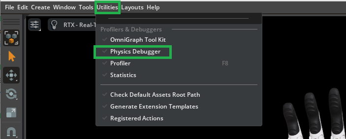
Open Utilities > Physics Debugger to show the Physics Debug panel.
Have the root prim
inspire_handselected. In Collision Mesh Debug Visualization, enable Solid Collision Mesh Visualization.
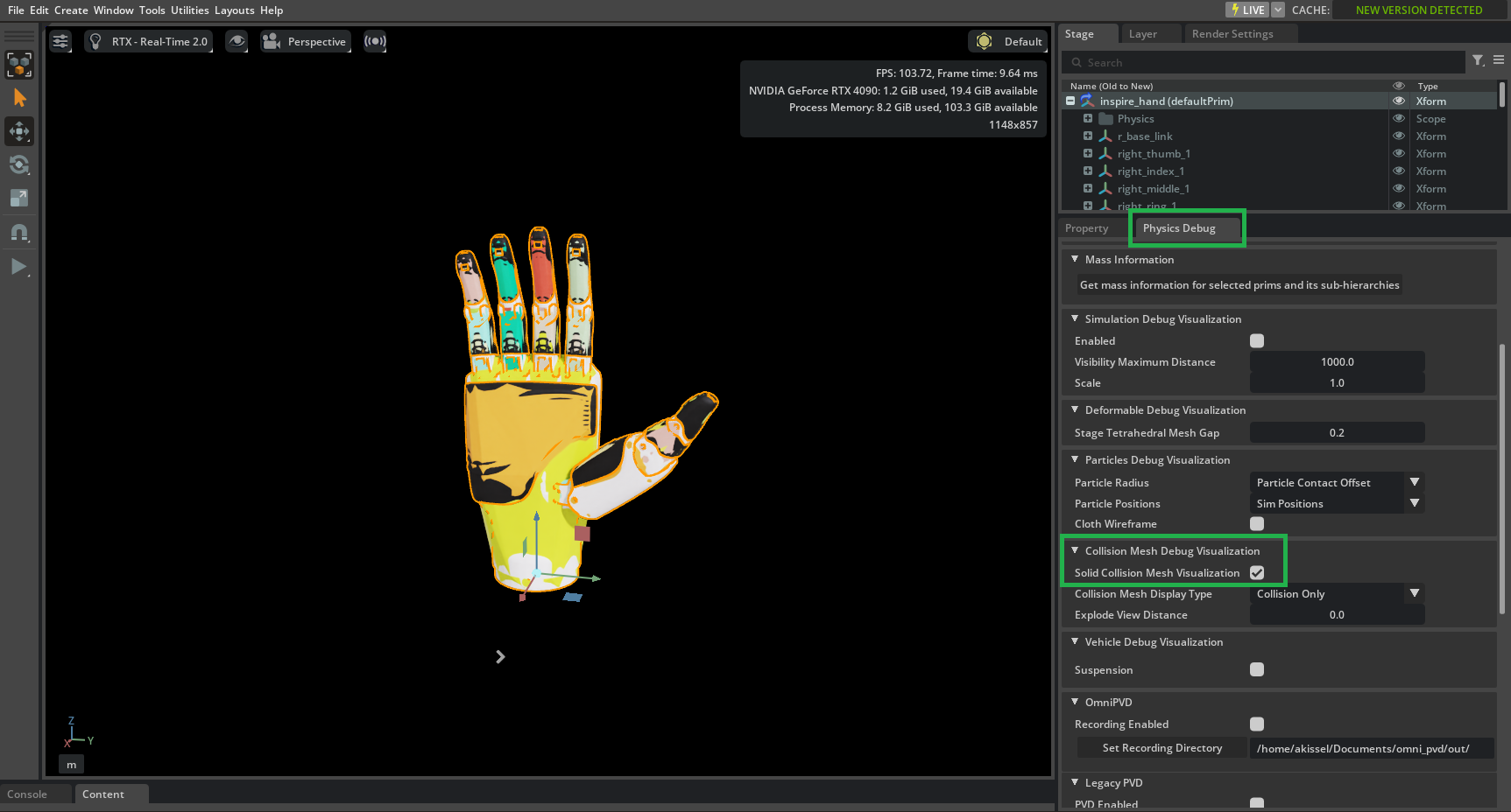
Tip
Solid Collision Mesh Visualization shows only the collision meshes for the currently selected prim. Ensure the inspire_hand prim is selected in the Stage panel so all collision meshes are visible.
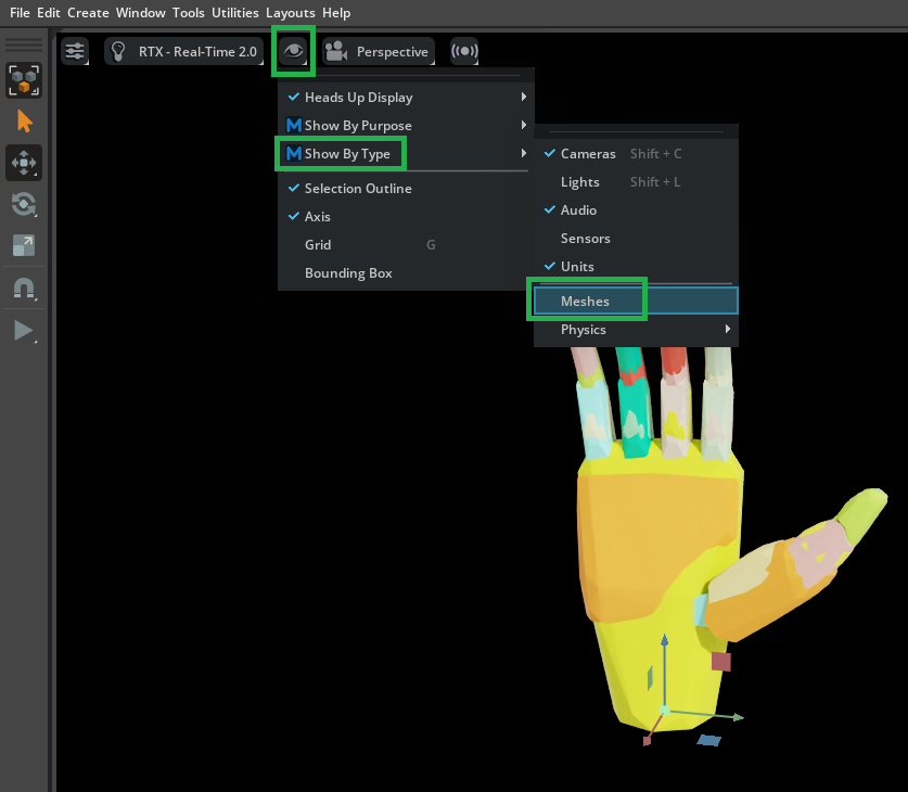
Open Eye > Show by Type > Meshes and turn Meshes off so the solid collision meshes are easier to see.
In the Stage panel, deactivate the
right_little_1link (lower pinky) to expose the overlapping collision shapes underneath—the rubber pad and surrounding links.
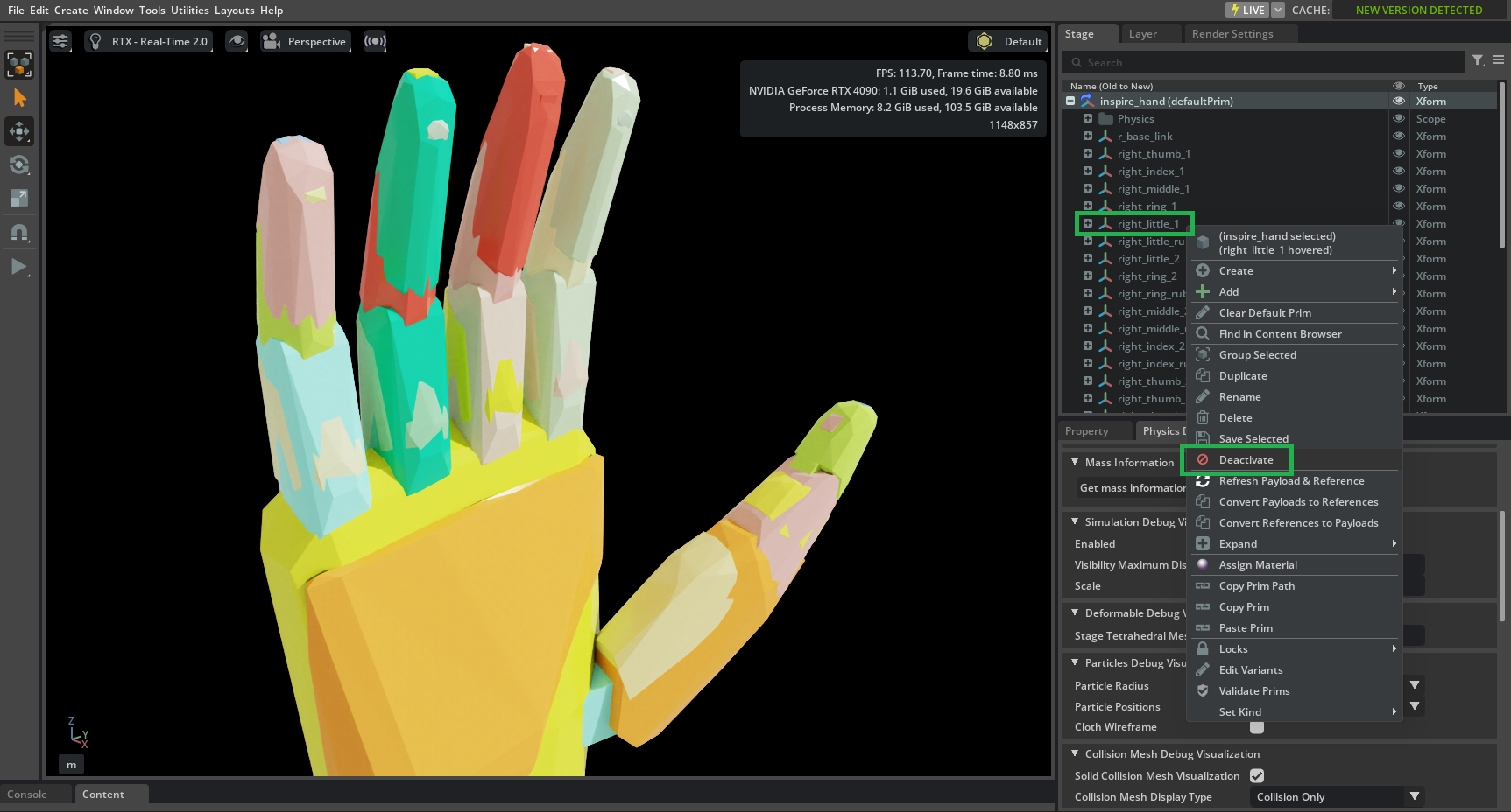
Identify where
right_little_rubber_1(lower pinky rubber pad) overlaps withr_base_link(palm)—that is where a problematic self-collision is likely to occur.

In the image above, with the lower pinky link hidden, the lower pinky rubber pad (tan/sand color) overlaps and collides with the palm (yellow). This is an example of a pair we will filter out to ensure stable simulation.
The schematic below shows which rigid body pairs of the pinky we will filter in this tutorial:

Open Eye > Show by Type > Meshes and toggle Meshes on to re-enable mesh visualization.
Module 3.3: Adding Filtered Pairs#
Next, we filter two specific self-collision pairs that drive pinky instability: (1) the palm r_base_link and the pinky’s lower rubber pad right_little_rubber_1, and (2) the lower pinky link right_little_1 and the upper rubber pad right_little_rubber_2.
Note
It doesn’t matter whether the filtered pair is a parent or child link; USD’s Physics Filtered Pairs block collisions between the specified pairs in both directions.
To follow Asset Structure 3.0, filtered pairs use the neutral Physics API—author on physics.usda.
Set physics.usda as the authoring layer#
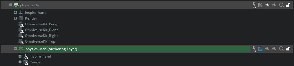
In the Layer tab, expand physx.usda. You should see physics.usda listed in the hierarchy.
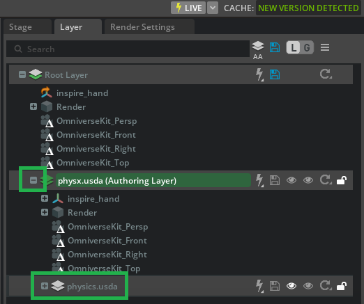
Right-click on physics.usda and select Set Authoring Layer.

You should now see the physics.usda layer highlighted green, indicating it is the active authoring layer.

Robot Self-Collision Detector: Filtered Pair#
Open Tools > Robotics > Asset Editors > Robot Self-Collision Detector (or bring the panel forward if it is already open).
Click Check Collisions so the table matches the current stage.
Find the row whose two bodies are
r_base_linkandright_little_rubber_1(column order may vary). Enable Filtered Pair for that row.Find the row for
right_little_1andright_little_rubber_2. Enable Filtered Pair for that row.
Tip
Multi-select rows and toggle one Filtered Pair checkbox to apply the same state to every selected row; see User Interface.
Toggling Filtered Pair authors UsdPhysics.FilteredPairsAPI on the active layer—the physics.usda authoring layer you set above.
Note
If you use the detector checkboxes in this section, skip the Property panel subsection that follows.
Verify and save#
Click on the blue files icon next to physics.usda (Authoring Layer) to save the changes to physics.usda.
Press Play. The pinky (little finger) should move more stably; the other fingers will still be unstable until their collision pairs are filtered the same way.

Note
Before starting Tutorial 5, open /path/to/Inspire/module_3_end-checkpoint_1/inspire_hand.usda. It includes all collision filters for stability, plus additional filtered pairs (e.g. finger tips and pads) for computational performance.
Property panel: Filtered Pairs on each prim#
The following steps add the same two relationships by editing Filtered Pairs on r_base_link and right_little_1. Use them if you prefer prim-by-prim authoring or want to see where the targets appear in the Property panel. If you already enabled both pairs in the Robot Self-Collision Detector, skip this subsection.
Palm and lower pinky rubber pad#
In the Stage tab, select the
r_base_linkprim. In the Property panel, click Add > Physics > Filtered Pairs.

With
r_base_linkstill selected, go to the Property panel. Find the Filtered Pairs section and click Add Target to add a new filtered collision pair.

In the pop-up that appears, browse or type to select
right_little_rubber_1.

After these steps, collisions between the palm (r_base_link) and the pinky’s lower rubber pad (right_little_rubber_1) are filtered out.
Lower pinky link and upper rubber pad#
In the Stage panel, select the
right_little_1prim (lower link of the pinky). In the Property panel, click Add > Physics > Filtered Pairs.

With
right_little_1still selected, go to the Property panel. Find the Filtered Pairs section and click Add Target to add a new filtered collision pair.In the pop-up window, browse or type to select
right_little_rubber_2(the upper pinky rubber pad), and confirm the selection.

Save the layers as in Verify and save above and then press Play again to confirm the pinky moves more stably.
Summary#
This tutorial covered:
How Filtered Pairs work and when to use them to prevent invalid self-collisions.
Enabling self-collisions, running the Robot Self-Collision Detector to list overlapping pairs and mark Filtered Pair, and using the Physics Debugger for solid collision mesh visualization when helpful.
Authoring the pinky’s two filters on physics.usda via the detector or the Property panel on
r_base_linkandright_little_1.
Next Steps#
Continue to Tutorial 5: Joint Drive Tuning to set drive limits (max force, max velocity) from the Inspire Hand specs, then to Tutorial 6: Joint Gains Tuning for stiffness and damping with the Gain Tuner.