Tutorial 13: Rigging a Legged Robot for a Locomotion Policy#
This tutorial explains how to rig a legged robot to match the configuration specified by a locomotion policy. The Isaac Sim Policy Controller Class already handles robot rigging at runtime for inference in Isaac Sim, so this tutorial is only relevant when you want to run the robot policy from an external process, such as ROS.
Learning Objectives#
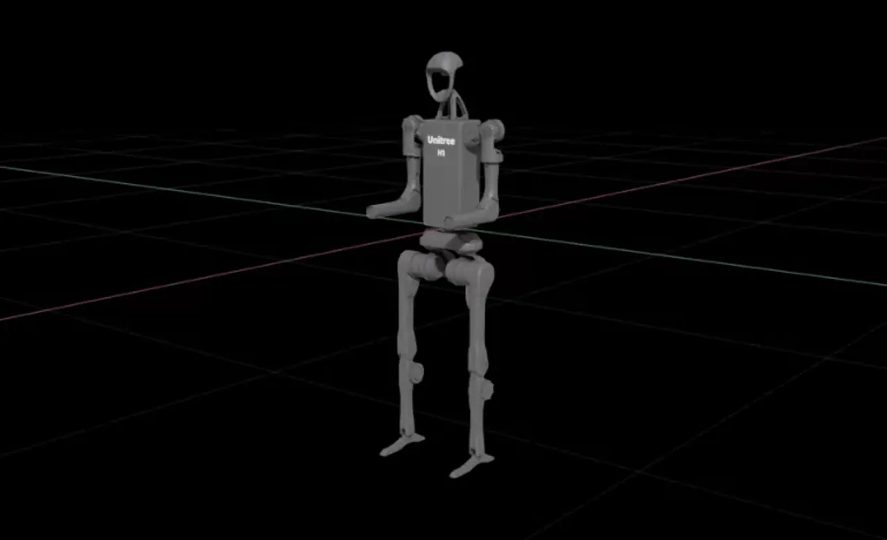
In this tutorial, you will walk through the process of rigging an H1 humanoid robot to match the configuration specified by the H1 flat terrain locomotion policy.
Setting the initial robot position
Setting the joint configuration
Verifying the joint configuration
Note
The H1 flat terrain policy environment definition file is available here.
Setting the Initial Robot Position#
The initial joint position of the robot is specified under the robot:init_state:joint_pos section of the environment definition file. The joint names are specified using the .* wildcard.
 1robot:
 2  init_state:
 3    joint_pos:
 4      .*_hip_yaw: 0.0
 5      .*_hip_roll: 0.0
 6      .*_hip_pitch: -0.28
 7      .*_knee: 0.79
 8      .*_ankle: -0.52
 9      torso: 0.0
10      .*_shoulder_pitch: 0.28
11      .*_shoulder_roll: 0.0
12      .*_shoulder_yaw: 0.0
13      .*_elbow: 0.52
14    joint_vel:
15      .*: 0.0
Note
The joint positions are specified in radians, whereas USD joint positions are specified in degrees.
To store the initial state of the robot:
Open the
h1.usdfile from the Content Browser atIsaac Sim/Robots/Unitree/H1.In the upper-right corner of the stage, select the
funnelicon and clickPhysics Jointsto filter the joint list.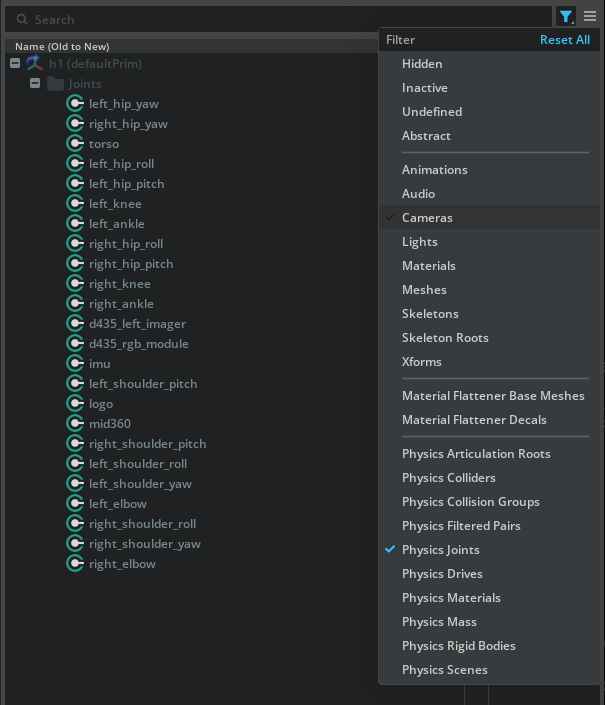
Left-click the first joint (
left_hip_yaw), then Shift-left-click the last joint (right_elbow) to select all joints.Right-click any selected joint and click Add > Physics > Joint State Angular to create a Joint State API attribute on the joints.
Right-click any selected joint and click Add > Physics > Angular drive to create a joint drive API attribute on the joints.
Note
The Joint State Angular API reports the joint position and velocity, and the Angular drive API drives the joint. If the joint already has a Joint State Angular API or Angular drive API, you can skip the previous two steps.
For each active joint, convert the
joint_posandjoint_velvalues from radians to degrees.Left-click the joint you are changing.
In the Property panel, scroll down to the
Target Positionattribute.Set the
Target Positionattribute to the converted value from thejoint_posattribute in the environment definition file.Set the
Target Velocityattribute to the converted value from thejoint_velattribute in the environment definition file.Repeat the previous steps for each active joint.
Press play.
Note
When using Newton, physics initialization might fail because reversed joints are not supported for /h1/Joints/torso. If this happens, select the torso joint. In the Property panel, go to Physics > Joint and swap the joint bodies so Body 0 is /h1/torso_link and Body 1 is /h1/pelvis.
Verify that the robot moves to the initial position specified in the environment definition file. To make the robot start in the initial position when the simulation starts, store the data in the Joint State API.
To prevent the robot from falling indefinitely, add a fixed joint between the robot and the world by right-clicking
/h1/torso_linkand selecting Create > Physics > Joint > Fixed Joint.
To save the robot pose:
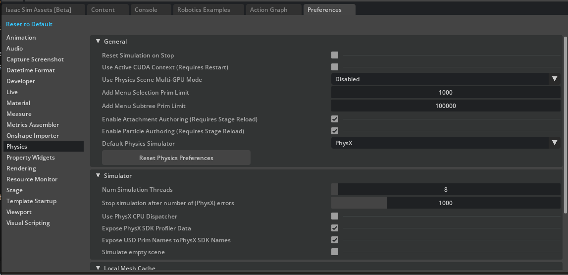
In the upper-left corner of the stage, click Edit > Preferences.
In the Preferences window, click the Physics tab in the left sidebar.
Uncheck Reset Simulation on Stop.
Play the simulation and stop it when the robot reaches the desired initial pose. Repeat this step once more to ensure the pose is saved even after reset.
Delete the fixed joint between the robot and the world.
Press Ctrl+S to save the USD file.
Check Reset Simulation on Stop again.
Setting the Joint Configuration#
Set the joint configuration to match the policy’s robot configuration. This may be different from the values stored in the USD file.
The joint drive configuration is specified under the scene:robot:actuators section of the environment definition file.
The following snippet shows the actuator configuration for the H1 robot legs.
 1actuators:k
 2  legs:
 3    class_type: omni.isaac.lab.actuators.actuator_pd:ImplicitActuator
 4    joint_names_expr:
 5    - .*_hip_yaw
 6    - .*_hip_roll
 7    - .*_hip_pitch
 8    - .*_knee
 9    - torso
10    effort_limit: 300
11    velocity_limit: 100.0
12    stiffness:
13      .*_hip_yaw: 150.0
14      .*_hip_roll: 150.0
15      .*_hip_pitch: 200.0
16      .*_knee: 200.0
17      torso: 200.0
18    damping:
19      .*_hip_yaw: 5.0
20      .*_hip_roll: 5.0
21      .*_hip_pitch: 5.0
22      .*_knee: 5.0
23      torso: 5.0
24    armature: null
25    friction: null
The joint_names_expr is a list of joint names to be controlled by the actuator. The class_type is the actuator type.
The effort_limit is the maximum effort that can be applied to the joint. The velocity_limit is the maximum velocity that can be applied to the joint.
The stiffness defines the joint stiffness. The damping defines the joint damping. The armature defines the joint armature, and the friction defines the joint friction.
To set the joint configurations:
Left-click a joint, such as
left_hip_yaw.In the Property panel, scroll down to the
Joint Driveattribute and setstiffnessanddampingto the values specified in the environment definition file.
Note
Remember to convert stiffness and damping to degree-based units.
The USD file stiffness is in \(\frac{kg \cdot m^2}{deg \cdot s^2}\) and the damping is in \(\frac{kg \cdot m^2}{deg \cdot s}\). To convert radians to degrees, you can use the following formulas:
The effort_limit is the maximum effort that can be applied to the joint. Set that value to the Max Force attribute of the joint drive API.
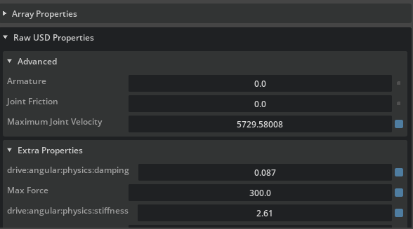
Scroll down to Raw USD Properties under the Advanced tab, and set the Armature and Joint Friction attributes to the values specified in the environment definition file.
For the Maximum Joint Velocity attribute, set it to the velocity_limit value specified in the environment definition file. Remember to convert it to degrees.
Note
Remember to set the joint configurations for all active joints in the robot, such as the arms and legs.
Verifying the Joint Configuration#
To verify the joint configuration, you can play the simulation and run the following snippet in Script Editor to print the joint configuration.
Play the simulation.
Open Script Editor by clicking Window > Script Editor.
Copy and paste the following snippet into Script Editor.
Run the snippet by clicking the Run button.
from isaacsim.core.experimental.prims import Articulation

prim = Articulation("/h1")
print(prim.dof_names)
lower, upper = prim.get_dof_limits()
stiffnesses, dampings = prim.get_dof_gains()
max_velocities = prim.get_dof_max_velocities()
max_efforts = prim.get_dof_max_efforts()
for i, name in enumerate(prim.dof_names):
    print(
        f"  {name}: lower={lower.numpy()[0][i]:.4f}, upper={upper.numpy()[0][i]:.4f}, "
        f"maxVelocity={max_velocities.numpy()[0][i]:.2f}, maxEffort={max_efforts.numpy()[0][i]:.0f}, "
        f"stiffness={stiffnesses.numpy()[0][i]:.2f}, damping={dampings.numpy()[0][i]:.2f}"
    )
Verify that you see console output similar to the following:
['left_hip_yaw', 'right_hip_yaw', 'torso', 'left_hip_roll', 'right_hip_roll', 'left_shoulder_pitch', 'right_shoulder_pitch', 'left_hip_pitch', 'right_hip_pitch', 'left_shoulder_roll', 'right_shoulder_roll', 'left_knee', 'right_knee', 'left_shoulder_yaw', 'right_shoulder_yaw', 'left_ankle', 'right_ankle', 'left_elbow', 'right_elbow']
  left_hip_yaw: lower=-0.4300, upper=0.4300, maxVelocity=100.00, maxEffort=300, stiffness=149.54, damping=5.00
  right_hip_yaw: lower=-0.4300, upper=0.4300, maxVelocity=100.00, maxEffort=300, stiffness=149.54, damping=5.00
  torso: lower=-2.3500, upper=2.3500, maxVelocity=100.00, maxEffort=300, stiffness=200.00, damping=4.98
  left_hip_roll: lower=-0.4300, upper=0.4300, maxVelocity=100.00, maxEffort=300, stiffness=149.54, damping=5.00
  right_hip_roll: lower=-0.4300, upper=0.4300, maxVelocity=100.00, maxEffort=300, stiffness=149.54, damping=5.00
  left_shoulder_pitch: lower=-2.8700, upper=2.8700, maxVelocity=100.00, maxEffort=300, stiffness=40.00, damping=10.00
  right_shoulder_pitch: lower=-2.8700, upper=2.8700, maxVelocity=100.00, maxEffort=300, stiffness=40.00, damping=10.00
  left_hip_pitch: lower=-3.1400, upper=2.5300, maxVelocity=100.00, maxEffort=300, stiffness=199.96, damping=5.00
  right_hip_pitch: lower=-3.1400, upper=2.5300, maxVelocity=100.00, maxEffort=300, stiffness=199.96, damping=5.00
  left_shoulder_roll: lower=-0.3400, upper=3.1100, maxVelocity=100.00, maxEffort=300, stiffness=40.00, damping=10.00
  right_shoulder_roll: lower=-3.1100, upper=0.3400, maxVelocity=100.00, maxEffort=300, stiffness=40.00, damping=10.00
  left_knee: lower=-0.2600, upper=2.0500, maxVelocity=100.00, maxEffort=300, stiffness=200.00, damping=4.98
  right_knee: lower=-0.2600, upper=2.0500, maxVelocity=100.00, maxEffort=300, stiffness=200.00, damping=4.98
  left_shoulder_yaw: lower=-1.3000, upper=4.4500, maxVelocity=100.00, maxEffort=300, stiffness=40.00, damping=10.00
  right_shoulder_yaw: lower=-4.4500, upper=1.3000, maxVelocity=100.00, maxEffort=300, stiffness=40.00, damping=10.00
  left_ankle: lower=-0.8700, upper=0.5200, maxVelocity=100.00, maxEffort=100, stiffness=20.00, damping=4.00
  right_ankle: lower=-0.8700, upper=0.5200, maxVelocity=100.00, maxEffort=100, stiffness=20.00, damping=4.00
  left_elbow: lower=-1.2500, upper=2.6100, maxVelocity=100.00, maxEffort=300, stiffness=40.00, damping=10.00
  right_elbow: lower=-1.2500, upper=2.6100, maxVelocity=100.00, maxEffort=300, stiffness=40.00, damping=10.00
The limit values in the console output are in radians. Each line shows the properties for a single DOF.
Verify that the maxVelocity, maxEffort, stiffness, and damping values match the values specified in the environment definition file.
For example, for left_hip_yaw, the max velocity is 100.0, the max effort is 300.0, the stiffness is 150.0, and the damping is 5.0.
Note
The rigged H1 robot is available in the Content Browser at Isaac/Samples/Rigging/H1/h1_rigged.usd.
Summary#
This tutorial covers the following topics:
Setting the initial robot position
Setting the joint configuration
Verifying the joint configuration