Tutorial 8: Generate Robot Configuration File#
Learning Objectives#
This is the third manipulator tutorial in a series of four tutorials. This tutorial will show you how to generate the robot configuration file for the UR10e robot from Universal Robots and the 2F-140 gripper from Robotiq. These robot configuration files provide information about the robot’s kinematics, dynamics, and other properties that are used in RMPFlow and cuMotion motion planners.
30 Minutes Tutorial
Prerequisites#
Review Tutorial 7: Configure a Manipulator tutorial prior to beginning this tutorial, continue the following steps from the asset built in the previous tutorial.
Note
If you have not completed the previous tutorial, you can find the prebuilt asset in the content browser at Isaac Sim/Samples/Rigging/Manipulator/configure_manipulator/ur10e/ur/ur_gripper.usd.
Generate Robot URDF#
Generate the robot URDF file from the UR10e robot and the 2F-140 gripper.
Enable the Isaac Sim USD to URDF Exporter Extension#
Go to Window > Extensions.
Type URDF in the search box, and find the Isaac Sim USD to URDF Exporter Extension.
If you can’t find it, remove the @feature filter from the search box.
Enable the extension by clicking the toggle button labeled ENABLE.
Check the box for AUTOLOAD, just to the right of ENABLE.
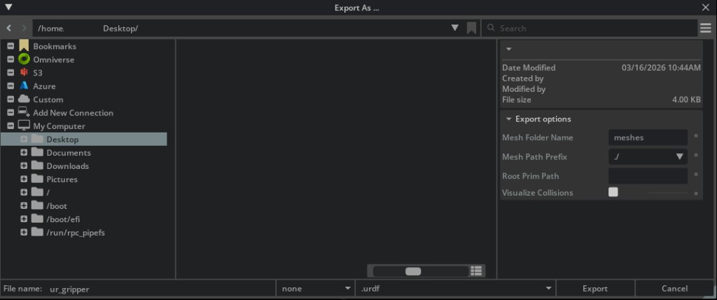
Export the URDF File#
Open the
ur_gripper.usdasset you made in the previous tutorial, or use the completed asset provided above.Click File > Export URDF.
In File name on the bottom left corner, save the file name to
robot.urdf.Tip
Using
robot.urdfmatches the default--urdfvalue in the pick-and-place tutorial scripts, so you won’t need to pass--urdfexplicitly when running them.In the Mesh Directory Path field, select the correct folder path to save the URDF meshes.
Click Export.
Note
Learn more about the USD to URDF Exporter Extension in the USD to URDF Exporter Extension manual.
Generate Robot Description Files and Collision Spheres#
Generate the XRDF file and collision spheres for the UR10e robot and the 2F-140 gripper.
Enable the Robot Description Editor Extension#
Go to Window > Extensions.
Search for
isaacsim.robot_setup.xrdf_editorand find the cuMotion/Lula Robot Description Editor extension.If you can’t find it, remove the @feature filter from the search box.
Enable the extension by clicking the toggle button labeled ENABLE.
Check the box for AUTOLOAD, just to the right of ENABLE.
Prepare the Robot Asset#
The Robot Description Editor does not support instanceable meshes. You must prepare the robot asset by disabling instanceable meshes.
Open the
ur_gripper.usdasset you made in the previous tutorial, or use the completed asset provided above.Select all
visualsandcollisionsprims on the stage.In the Property panel, uncheck the Instanceable checkbox for each.
Hint
You can use the search feature to find the
visualsandcollisionsprims by searching forvisualsandcollisionsrespectively.

The Instanceable checkbox (highlighted in red) should be unchecked for all geometry prims.#
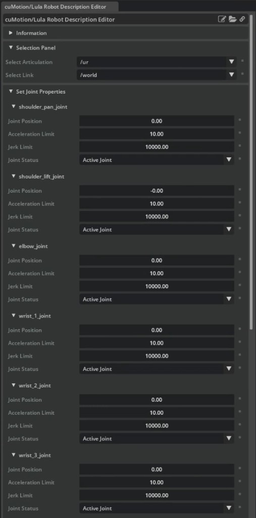
Configure Joint Properties#
Press Play to start the simulation.
Open the editor via Tools > Robotics > cuMotion/Lula Robot Description Editor.
In the Selection Panel, set Select Articulation to the ur articulation prim path.
In Set Joint Properties, assign each joint a Joint Status:
Mark each Universal Robots arm joint as Active Joint. These joints are directly controlled by cuMotion.
Keep the Robotiq 2F-140 gripper joints as Fixed Joint. cuMotion holds these joints at the specified default position.
Important
Do not stop the simulation, you will need it to generate the collision spheres.
Pay attention to the default joint positions for fixed joints. They should match the initial pose defined in the manipulator USD, or you will need to reset the robot to those positions during task initialization.
Generate Collision Spheres#
Important
Do not stop the simulation or exit the Robot Description Editor during this step, or you will need to redo the previous steps.
Repeat the following for each link in the ur articulation, including gripper links:
In the Selection Panel, select the link under Select Link. Use upper_arm_link as an example.
In Link Sphere Editor > Generate Spheres, select a mesh from the Select Mesh dropdown (e.g.
/collisions/upperarm/mesh).Set the Radius Offset and Number of Spheres (e.g.
0.03and8respectively).Optionally adjust sphere positions by clicking and dragging them in the viewport.
Click GENERATE SPHERES. The spheres will turn cyan when finalized.
Suggested per-link sphere settings (ur10e + Robotiq 2F-140)
For links with multiple mesh entries, generate spheres for each mesh and combine them on the same link.
Select Link |
Number of Spheres |
Radius Offset |
Select Mesh |
|---|---|---|---|
|
1 |
0.03 |
|
|
8 |
0.03 |
|
|
8 |
0.03 |
|
|
1 |
0.03 |
|
|
1 |
0.02 |
|
|
1 |
0.02 |
|
|
1 |
0.02 |
|
|
2 |
0.02 |
|
|
2 |
0.02 |
|
|
2 |
0.02 |
|
|
2 |
0.02 |
|
|
2 |
0.02 |
|
|
2 |
0.02 |
|
|
2 |
0.02 |
|
|
2 |
0.02 |
|
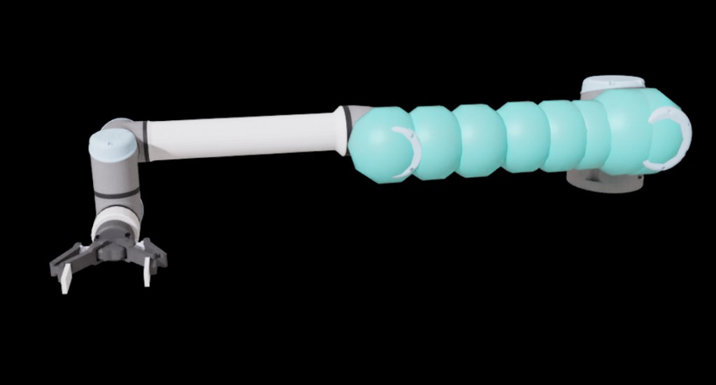
Spheres generated for the upper_arm_link.#
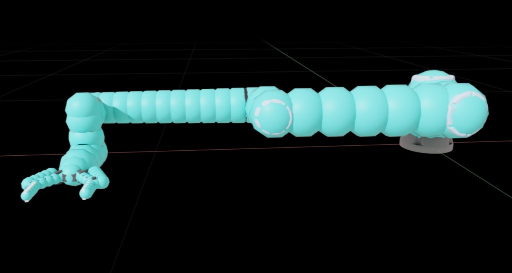
Spheres generated for the full ur10e robot.#
General tuning tips
Size spheres to cover the link without being oversized — large spheres cause solver conservatism.
More spheres improves collision accuracy but reduces solver performance.
For long cylindrical links, generate spheres on the ends and use Connect Spheres to fill the middle evenly.
Use Scale Spheres in Link to resize spheres uniformly across a link.
The auto-generator requires water-tight triangle meshes. If it fails for a link, add and connect spheres manually.
Export to XRDF#
Important
Do not stop the simulation before exporting.
At the bottom of the Robot Description Editor, expand Export To File > Export to cuMotion XRDF.
Click the file icon and specify the file name as
robot.xrdf.Select the XRDF version to export (version 2.0 is recommended).
Click Save. Save to the same directory as the robot URDF file.
Stop the simulation after the file is exported.
Adding a Tool to the Robot Configuration#
cuMotion requires a tool frame defined in the XRDF file. The tool frame is used to specify the end-effector frame for the robot.
Open the
robot.xrdffile in a text editor.Add the following line to the file:
tool_frames: ["wrist_3_link"]
See Robot Configuration Tutorial for more information on XRDF files and loading robot configurations into cuMotion.
Assemble the Robot Configuration Directory#
The pick-and-place tutorial scripts and the load_cumotion_robot API expect all robot configuration files to live in a single directory. After completing the export steps above, your directory should look like this:
/path/to/robot/config/
├── robot.urdf
├── robot.xrdf
├── rmp_flow.yaml
└── meshes/
    └── ...
Pass this directory to the tutorial scripts with --xrdf-dir /path/to/robot/config. For a full description of these files and how they are used by cuMotion, see the Robot Configuration Files section of the cuMotion tutorial.
The rmp_flow.yaml file configures the RMPflow reactive motion controller. Save the text below in a file named rmp_flow.yaml and save it to the same directory as your robot.urdf and robot.xrdf files.
rmp_flow.yaml — RMPflow configuration example
format: rmpflow
api_version: 2.0

joint_limit_buffers: [.01, .01, .01, .01, .01, .01]

rmp_params:
    cspace_target_rmp:
        metric_scalar: 50.
        position_gain: 100.
        damping_gain: 50.
        robust_position_term_thresh: .5
        inertia: 1.
    cspace_trajectory_rmp:
        p_gain: 80.
        d_gain: 10.
        ff_gain: .25
        weight: 50.
    cspace_affine_rmp:
        final_handover_time_std_dev: .25
        weight: 2000.
    joint_limit_rmp:
        metric_scalar: 1000.
        metric_length_scale: .01
        metric_exploder_eps: 1e-3
        metric_velocity_gate_length_scale: .01
        accel_damper_gain: 200.
        accel_potential_gain: 1.
        accel_potential_exploder_length_scale: .1
        accel_potential_exploder_eps: 1e-2
    joint_velocity_cap_rmp:
        max_velocity: 2.15
        velocity_damping_region: 0.5
        damping_gain: 300.
        metric_weight: 100.
    target_rmp:
        accel_p_gain: 80.
        accel_d_gain: 120.
        accel_norm_eps: .075
        metric_alpha_length_scale: .05
        min_metric_alpha: .01
        max_metric_scalar: 10000.
        min_metric_scalar: 2500.
        proximity_metric_boost_scalar: 20.
        proximity_metric_boost_length_scale: .02
        accept_user_weights: false
    axis_target_rmp:
        accel_p_gain: 200.
        accel_d_gain: 40.
        metric_scalar: 10.
        proximity_metric_boost_scalar: 3000.
        proximity_metric_boost_length_scale: .05
        accept_user_weights: false
    collision_rmp:
        damping_gain: 50.
        damping_std_dev: .04
        damping_robustness_eps: 1e-2
        damping_velocity_gate_length_scale: .01
        repulsion_gain: 1000.
        repulsion_std_dev: .01
        metric_modulation_radius: .5
        metric_scalar: 500.
        metric_exploder_std_dev: .02
        metric_exploder_eps: .001
    damping_rmp:
        accel_d_gain: 30.
        metric_scalar: 50.
        inertia: 100.

canonical_resolve:
    max_acceleration_norm: 50.
    projection_tolerance: .01
    verbose: false

body_capsules:
    - name: base_link
      pt1: [0, 0, 0.22]
      pt2: [0, 0, 0]
      radius: .09

body_collision_controllers:
  - name: wrist_2_link
    radius: .04
  - name: wrist_3_link
    radius: .04
Summary#
In this tutorial, you have learned how to generate the robot configuration files for the UR10e robot and the 2F-140 gripper using the Robot Description Editor and the USD to URDF Exporter Extension extensions. The resulting XRDF file can be loaded directly into cuMotion motion planners as described in Robot Configuration Tutorial.