Camera Sensors#
Cameras are modeled using the Camera USD prim type. Camera data is acquired from camera prims using render products, which can be created by multiple different extensions in Omniverse, including the omni.replicator extension.
Note
Isaac Sim camera functionality is based on Omniverse cameras.
GUI#
Creating and Modifying a Camera#
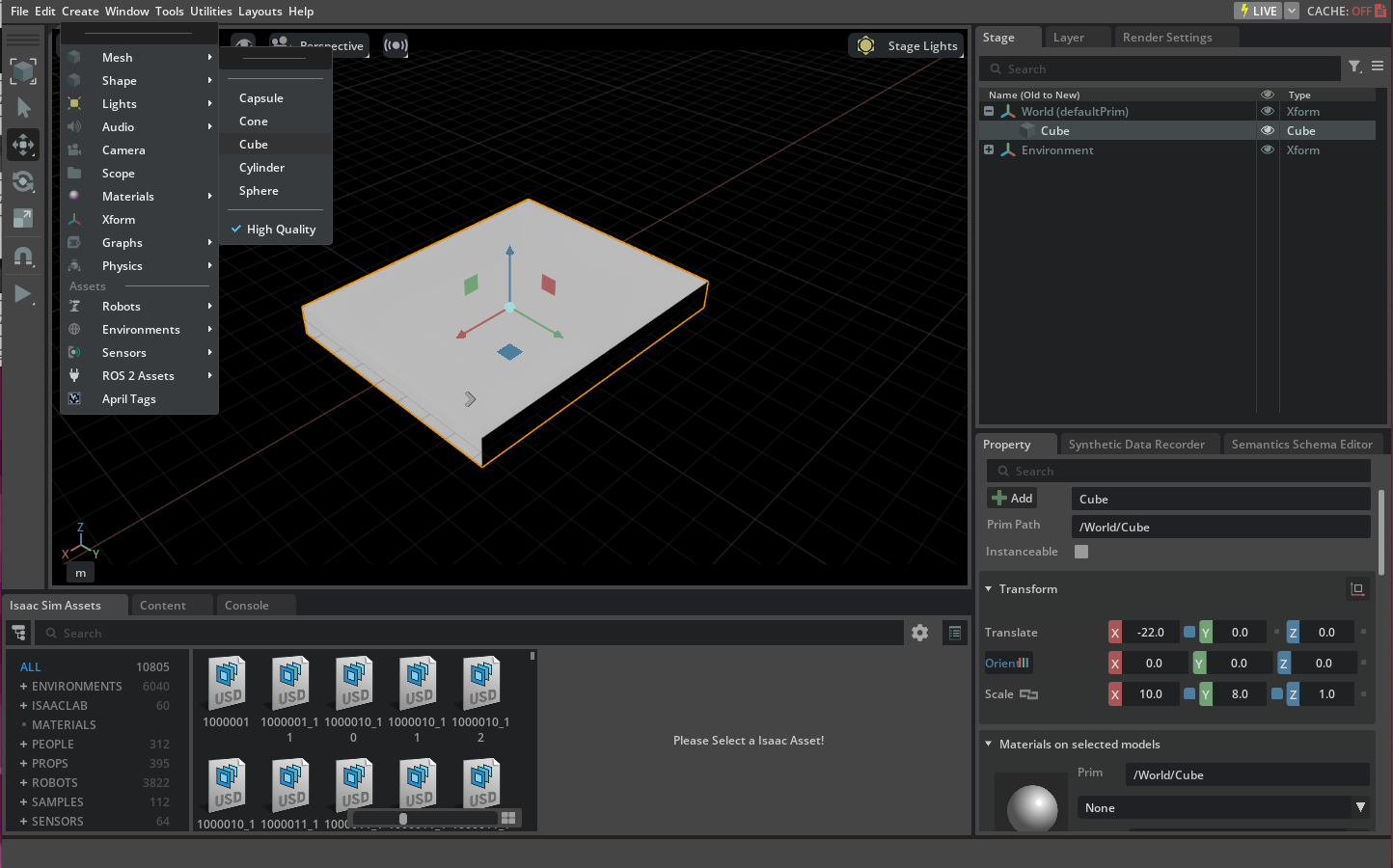
Create a cube by selecting Create > Shape > Cube and change its location and scale through the property panel as indicated in the screenshot below.
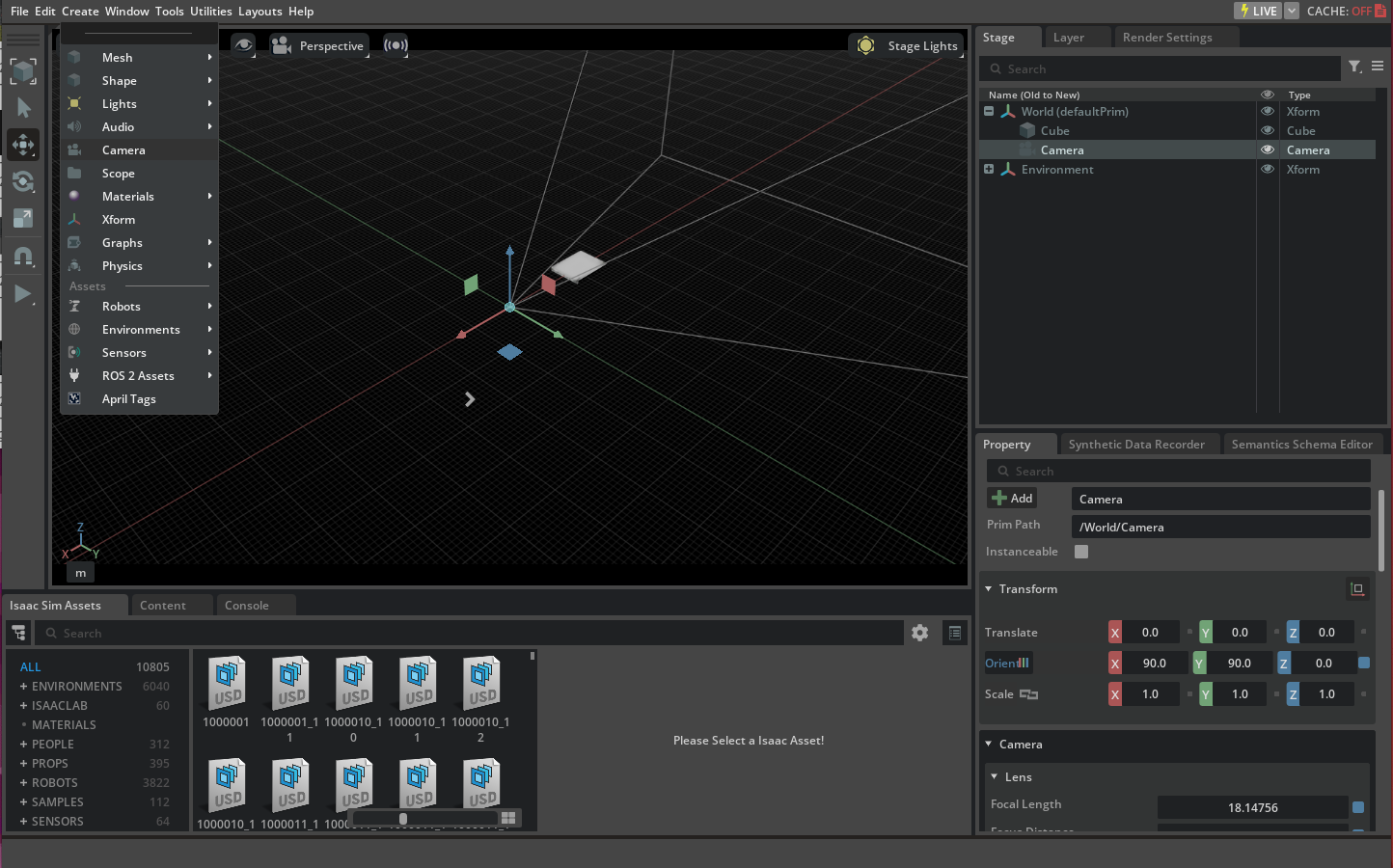
Create a camera prim by selecting Create > Camera and then select it from the stage window to view its field of view as indicated below.
In order to render the frames from the camera we can switch the default viewport (which is a render product itself) to the camera prim that you just created. Select the video icon at the top of the viewport window and then select the camera prim you just created under the
Camerasmenu.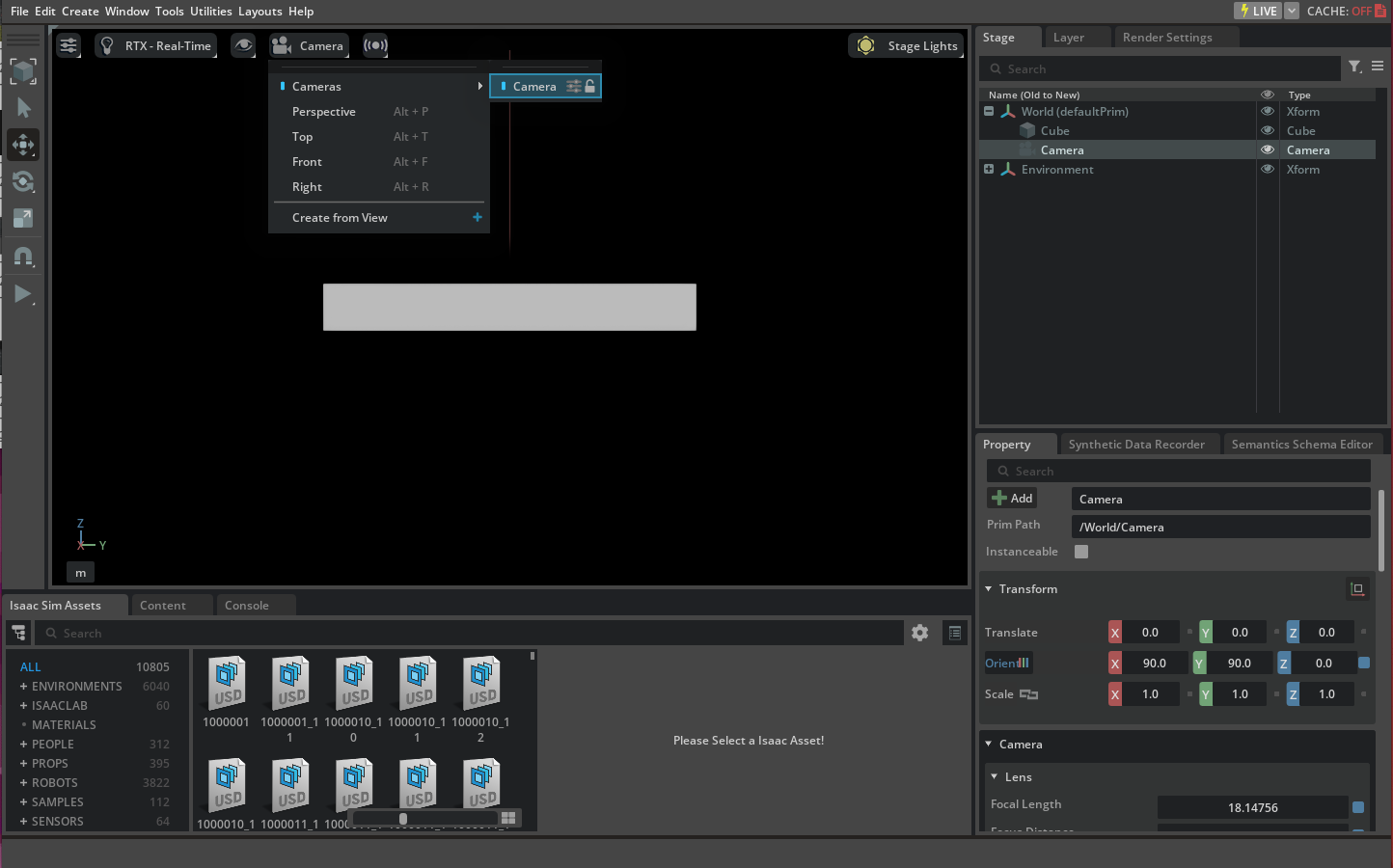
Standalone Python#
There are multiple ways to retrieve data from a render product attached to a camera prim in Isaac Sim. One method is the Camera class
under the isaacsim.sensors.camera extension. You may run an example using the Camera class via ./python.sh standalone_examples/api/isaacsim.sensors.camera/camera.py.
The code in that example is provided below, for reference.
1from isaacsim import SimulationApp
2
3simulation_app = SimulationApp({"headless": False})
4
5from isaacsim.core.api.objects import DynamicCuboid
6from isaacsim.sensors.camera import Camera
7from isaacsim.core.api import World
8import isaacsim.core.utils.numpy.rotations as rot_utils
9import numpy as np
10import matplotlib.pyplot as plt
11
12
13my_world = World(stage_units_in_meters=1.0)
14
15cube_2 = my_world.scene.add(
16 DynamicCuboid(
17 prim_path="/new_cube_2",
18 name="cube_1",
19 position=np.array([5.0, 3, 1.0]),
20 scale=np.array([0.6, 0.5, 0.2]),
21 size=1.0,
22 color=np.array([255, 0, 0]),
23 )
24)
25
26cube_3 = my_world.scene.add(
27 DynamicCuboid(
28 prim_path="/new_cube_3",
29 name="cube_2",
30 position=np.array([-5, 1, 3.0]),
31 scale=np.array([0.1, 0.1, 0.1]),
32 size=1.0,
33 color=np.array([0, 0, 255]),
34 linear_velocity=np.array([0, 0, 0.4]),
35 )
36)
37
38camera = Camera(
39 prim_path="/World/camera",
40 position=np.array([0.0, 0.0, 25.0]),
41 frequency=20,
42 resolution=(256, 256),
43 orientation=rot_utils.euler_angles_to_quats(np.array([0, 90, 0]), degrees=True),
44)
45
46my_world.scene.add_default_ground_plane()
47my_world.reset()
48camera.initialize()
49
50i = 0
51camera.add_motion_vectors_to_frame()
52
53while simulation_app.is_running():
54 my_world.step(render=True)
55 print(camera.get_current_frame())
56 if i == 100:
57 points_2d = camera.get_image_coords_from_world_points(
58 np.array([cube_3.get_world_pose()[0], cube_2.get_world_pose()[0]])
59 )
60 points_3d = camera.get_world_points_from_image_coords(points_2d, np.array([24.94, 24.9]))
61 print(points_2d)
62 print(points_3d)
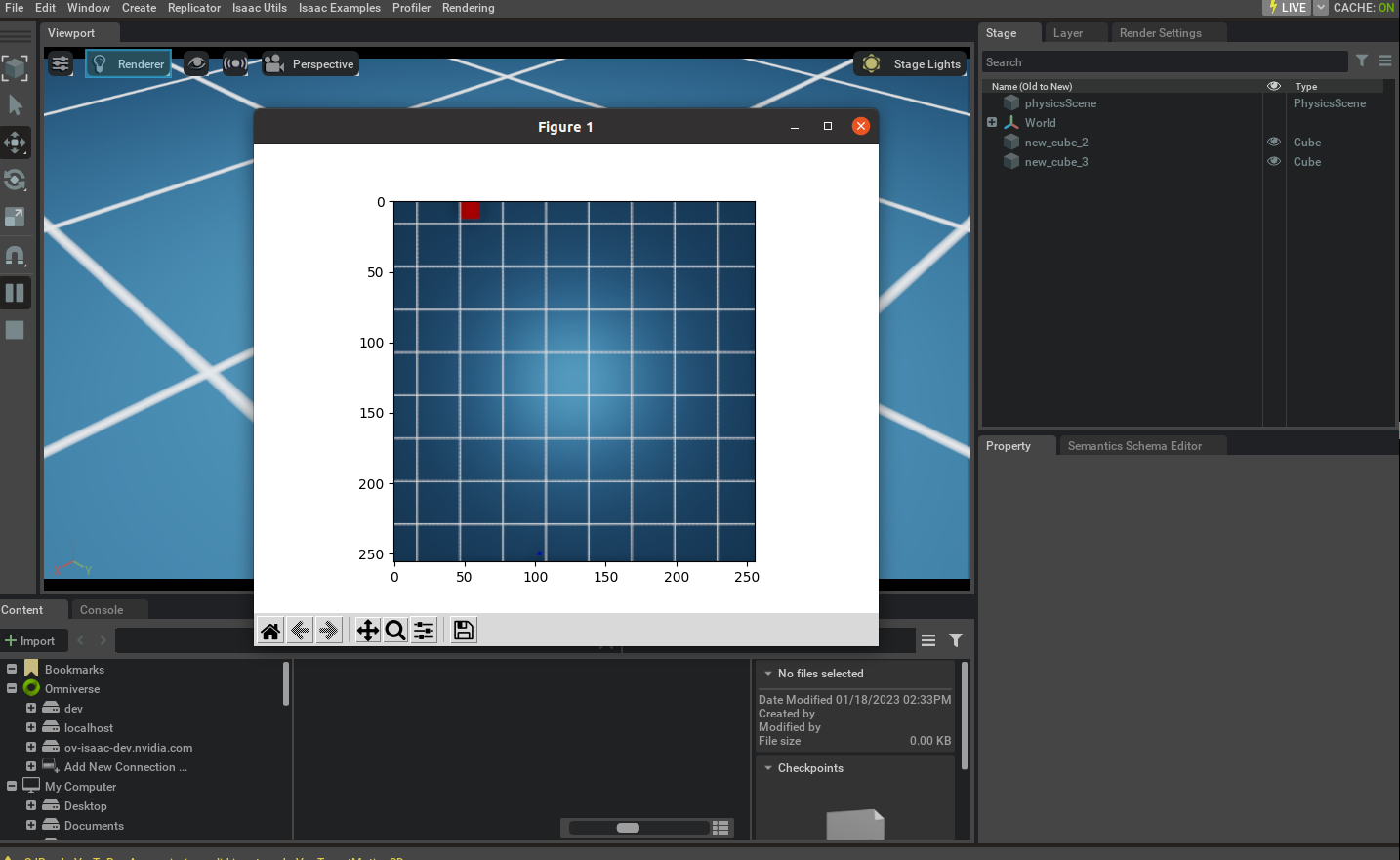
63 imgplot = plt.imshow(camera.get_rgba()[:, :, :3])
64 plt.show()
65 print(camera.get_current_frame()["motion_vectors"])
66 if my_world.is_playing():
67 if my_world.current_time_step_index == 0:
68 my_world.reset()
69 i += 1
70
71
72simulation_app.close()
Calibration and Camera Lens Distortion Models#
Omniverse cameras support a variety of lens distortion models, described here.
The isaacsim.sensors.camera.Camera class includes APIs to set lens distortion parameters for each Omniverse camera lens distortion model.
Calibration toolkits like OpenCV normally provide the calibration parameters as an intrinsic matrix and distortion coefficients. Omniverse includes native renderer support for the OpenCV pinhole and
OpenCV fisheye lens distortion models. Isaac Sim provides two standalone examples demonstrating the use of the Camera class with OpenCV lens distortion models,
located at standalone_examples/api/isaacsim.sensors.camera/camera_opencv_pinhole.py and standalone_examples/api/isaacsim.sensors.camera/camera_opencv_fisheye.py.
Portions of these examples are repeated below for reference, and can be run via the Script Editor, opened from Window > Script Editor.
Note
Previously, the Camera class included APIs to approximate OpenCV pinhole and fisheye models distortion parameters
by setting coefficients for the fisheyePolynomial distortion model. Now that OpenCV lens distortion models are natively
supported, those APIs have been deprecated.
Note
Omniverse RTX Camera Projection Attributes
have been deprecated as of Isaac Sim 5.0, in favor of the OmniLensDistortion schemata.
The deprecated attributes are still visible in the UI in the Fisheye Lens panel when selecting a Camera prim, but will be ignored if the user
has set an OmniLensDistortion schema instead. Follow the instructions in “How To Add Schemata to Cameras” to see how to update Camera prim
attributes for the new schemata in the UI.
OpenCV Fisheye#
import isaacsim.core.utils.numpy.rotations as rot_utils
import numpy as np
from isaacsim.core.api import World
from isaacsim.core.api.objects import DynamicCuboid
from isaacsim.core.utils.stage import add_reference_to_stage
from isaacsim.sensors.camera import Camera
from isaacsim.storage.native import get_assets_root_path
from PIL import Image, ImageDraw

# Desired image resolution, camera intrinsics matrix, and distortion coefficients
width, height = 1920, 1200
camera_matrix = [[455.8, 0.0, 943.8], [0.0, 454.7, 602.3], [0.0, 0.0, 1.0]]
distortion_coefficients = [0.05, 0.01, -0.003, -0.0005]

# Camera sensor size and optical path parameters. These parameters are not the part of the
# OpenCV camera model, but they are nessesary to simulate the depth of field effect.
#
# Note: To disable the depth of field effect, set the f_stop to 0.0. This is useful for debugging.
# Set pixel size (microns)
pixel_size = 3
# Set f-number, the ratio of the lens focal length to the diameter of the entrance pupil (unitless)
f_stop = 1.8
# Set focus distance (meters) - chosen as distance from camera to cube
focus_distance = 1.5

# Add a ground plane to the scene
usd_path = get_assets_root_path() + "/Isaac/Environments/Grid/default_environment.usd"
add_reference_to_stage(usd_path=usd_path, prim_path="/ground_plane")

# Add some cubes and a Camera to the scene
cube_1 = DynamicCuboid(
    prim_path="/new_cube_1",
    name="cube_1",
    position=np.array([0, 0, 0.5]),
    scale=np.array([1.0, 1.0, 1.0]),
    size=1.0,
    color=np.array([255, 0, 0]),
)

cube_2 = DynamicCuboid(
    prim_path="/new_cube_2",
    name="cube_2",
    position=np.array([2, 0, 0.5]),
    scale=np.array([1.0, 1.0, 1.0]),
    size=1.0,
    color=np.array([0, 255, 0]),
)

cube_3 = DynamicCuboid(
    prim_path="/new_cube_3",
    name="cube_3",
    position=np.array([0, 4, 1]),
    scale=np.array([2.0, 2.0, 2.0]),
    size=1.0,
    color=np.array([0, 0, 255]),
)

camera = Camera(
    prim_path="/World/camera",
    position=np.array([0.0, 0.0, 2.0]),  # 1 meter away from the side of the cube
    frequency=30,
    resolution=(width, height),
    orientation=rot_utils.euler_angles_to_quats(np.array([0, 90, 0]), degrees=True),
)
camera.initialize()

# Calculate the focal length and aperture size from the camera matrix
((fx, _, cx), (_, fy, cy), (_, _, _)) = camera_matrix  # fx, fy are in pixels, cx, cy are in pixels
horizontal_aperture = pixel_size * width * 1e-6  # convert to meters
vertical_aperture = pixel_size * height * 1e-6  # convert to meters
focal_length_x = pixel_size * fx * 1e-6  # convert to meters
focal_length_y = pixel_size * fy * 1e-6  # convert to meters
focal_length = (focal_length_x + focal_length_y) / 2  # convert to meters

# Set the camera parameters, note the unit conversion between Isaac Sim sensor and Kit
camera.set_focal_length(focal_length)
camera.set_focus_distance(focus_distance)
camera.set_lens_aperture(f_stop)
camera.set_horizontal_aperture(horizontal_aperture)
camera.set_vertical_aperture(vertical_aperture)

camera.set_clipping_range(0.05, 1.0e5)

# Set the distortion coefficients
camera.set_opencv_fisheye_properties(cx=cx, cy=cy, fx=fx, fy=fy, fisheye=distortion_coefficients)
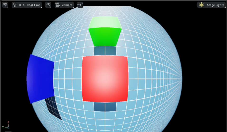
After running the snippet above and setting the viewport to the newly-created camera, you should see an image like the one below.
OpenCV Pinhole#
import isaacsim.core.utils.numpy.rotations as rot_utils
import numpy as np
from isaacsim.core.api import World
from isaacsim.core.api.objects import DynamicCuboid
from isaacsim.core.utils.stage import add_reference_to_stage
from isaacsim.sensors.camera import Camera
from isaacsim.storage.native import get_assets_root_path
from PIL import Image, ImageDraw

# Desired image resolution, camera intrinsics matrix, and distortion coefficients
width, height = 1920, 1200
camera_matrix = [[958.8, 0.0, 957.8], [0.0, 956.7, 589.5], [0.0, 0.0, 1.0]]
distortion_coefficients = [0.14, -0.03, -0.0002, -0.00003, 0.009, 0.5, -0.07, 0.017]

# Camera sensor size and optical path parameters. These parameters are not the part of the
# OpenCV camera model, but they are nessesary to simulate the depth of field effect.
#
# Note: To disable the depth of field effect, set the f_stop to 0.0. This is useful for debugging.
# Set pixel size (microns)
pixel_size = 3
# Set f-number, the ratio of the lens focal length to the diameter of the entrance pupil (unitless)
f_stop = 1.8
# Set focus distance (meters) - chosen as distance from camera to cube
focus_distance = 1.5

# Add a ground plane to the scene
usd_path = get_assets_root_path() + "/Isaac/Environments/Grid/default_environment.usd"
add_reference_to_stage(usd_path=usd_path, prim_path="/ground_plane")

# Add some cubes and a Camera to the scene
cube_1 = DynamicCuboid(
    prim_path="/new_cube_1",
    name="cube_1",
    position=np.array([0, 0, 0.5]),
    scale=np.array([1.0, 1.0, 1.0]),
    size=1.0,
    color=np.array([255, 0, 0]),
)

cube_2 = DynamicCuboid(
    prim_path="/new_cube_2",
    name="cube_2",
    position=np.array([2, 0, 0.5]),
    scale=np.array([1.0, 1.0, 1.0]),
    size=1.0,
    color=np.array([0, 255, 0]),
)

cube_3 = DynamicCuboid(
    prim_path="/new_cube_3",
    name="cube_3",
    position=np.array([0, 4, 1]),
    scale=np.array([2.0, 2.0, 2.0]),
    size=1.0,
    color=np.array([0, 0, 255]),
)

camera = Camera(
    prim_path="/World/camera",
    position=np.array([0.0, 0.0, 2.0]),  # 1 meter away from the side of the cube
    frequency=30,
    resolution=(width, height),
    orientation=rot_utils.euler_angles_to_quats(np.array([0, 90, 0]), degrees=True),
)
camera.initialize()

# Calculate the focal length and aperture size from the camera matrix
((fx, _, cx), (_, fy, cy), (_, _, _)) = camera_matrix  # fx, fy are in pixels, cx, cy are in pixels
horizontal_aperture = pixel_size * width * 1e-6  # convert to meters
vertical_aperture = pixel_size * height * 1e-6  # convert to meters
focal_length_x = pixel_size * fx * 1e-6  # convert to meters
focal_length_y = pixel_size * fy * 1e-6  # convert to meters
focal_length = (focal_length_x + focal_length_y) / 2  # convert to meters

# Set the camera parameters, note the unit conversion between Isaac Sim sensor and Kit
camera.set_focal_length(focal_length)
camera.set_focus_distance(focus_distance)
camera.set_lens_aperture(f_stop)
camera.set_horizontal_aperture(horizontal_aperture)
camera.set_vertical_aperture(vertical_aperture)

camera.set_clipping_range(0.05, 1.0e5)

# Set the distortion coefficients
camera.set_opencv_pinhole_properties(cx=cx, cy=cy, fx=fx, fy=fy, pinhole=distortion_coefficients)
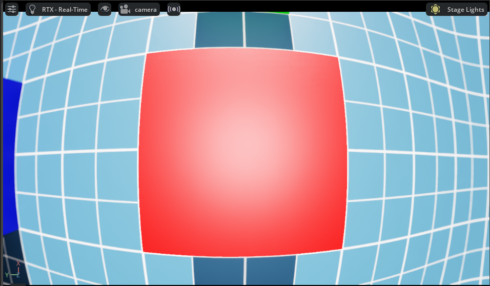
After running the snippet above and setting the viewport to the newly-created camera, you should see an image like the one below.
Extrinsic Calibration#
Extrinsic calibration parameters are normally provided by the calibration toolkits in a form of a transformation matrix. The convention between the axis and rotation order is important and it varies between the toolkits.
To set the extrinsic parameters for the individual camera sensor, use the following example to convert the transformation matrix from the calibration toolkit to the Isaac Sim units:
 1import numpy as np
 2import isaacsim.core.utils.numpy.rotations as rot_utils       # convenience functions for quaternion operations
 3
 4dX,dY,dZ = ...  # Extrinsics translation vector from the calibration toolkit
 5rW,rX,rY,rZ =   # Note the order of the rotation parameters, it depends on the toolkit
 6
 7Camera(
 8    prim_path="/rig/camera_color",
 9    position    =  np.array([-dZ, dX, dY])      # Note, translation in the local frame of the prim
10    orientation =  np.array([rW, -rZ, rX, rY])  # quaternion orientation in the world/ local frame of the prim
11                                                # (depends if translation or position is specified)
12)
As an alternative, the camera sensor can be attached to a prim. In that case, the camera sensor will inherit the position and orientation from the prim.
 1import isaacsim.core.utils.prims as prim_utils
 2
 3camera_prim = prim_utils.create_prim(
 4    name,
 5    "Xform",
 6    translation = ...
 7    orientation = ...
 8)
 9
10camera = Camera(
11    prim_path=f"{name}/camera",
12    ...
13)
Creating Camera Sensor Rigs#
The camera sensor rig is a collection of camera sensors that are attached to a single prim. It can be assembled from the individual sensors, that are either created manually or derived from the calibration parameters.
This will be a short discussion on how we created a digital twin of the Intel® RealSense™ Depth Camera D455. The USD for the camera can be found in the content folder as: `/Isaac/Sensors/Intel/RealSense/rsd455.usd.
There are three visual sensors, and one IMU sensor on the RealSense. Their placement relative to the camera origin was taken from the layout diagram in the TechSpec document from Intel’s web site.
Most camera parameters were also found in the TechSpec, for example, the USD parameter fStop is the denominator of the F Number from the TechSpec; the focalLength is the Focal Length, and the ftheatMaxFov
is the Diagonal Field of View. However, some parameters, like the focusDistance were estimated by comparing real output and informed guesses.
The horizontalAperture and verticalAperture in that example are derived from the technical specification. From the TechSpec, the left, right, and color sensors are listed as a OmniVision Technologies OV9782, and
the Tech Spec for that sensor lists the image area as 3896 x 2453 µm. We used that as the aperture sizes.
The resolution for the depth and color cameras are 1280 x 800, but it’s up to the user to attach a render product of that size to the outputs.
The Pseudo Depth camera is a stand in for the depth image created by the camera’s firmware. We don’t attempt to copy the algorithms that create the image from stereo, but the Camera_Pseudo_Depth component
is a convenience camera that can return the scene depth as seen from that camera position between the left and right stereo cameras. It would be more accurate to create a depth image from stereo, and if
the same algorithm that is used in the RealSense was used then the same results (including artifacts) would be produced.
Camera Inspector Extension#
The Camera Inspector Extension allows you to:
Create multiple viewports for each camera
Check camera coverage
Get and set camera poses in the desired frames
Launching Extension#
To open the Camera Inspector extension:
Go to the Menu Bar.
Select Tools > Sensors > Camera Inspector.
After launching the extension, verify that you can see your camera in the dropdown.
When adding a new camera, you must click the Refresh button to ensure that the extension finds this new camera.
Select the camera you want to inspect.
Camera State Textbox#
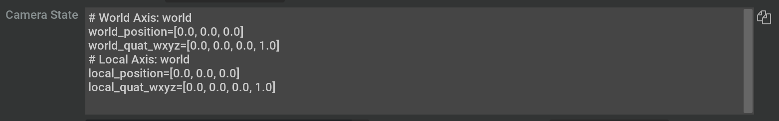
The Camera State textbox near the top of the extension provides a convenient way to copy the position and orientation of your camera directly into code. Click the copy icon on the right of the textbox to copy to your clipboard.
Creating a Viewport#
With the camera selected, you can create a new viewport for your camera.
Click on the ‘Create Viewport’ button to the right of the camera dropdown menu.
By default, this creates a new viewport and assigns the current selected Camera to it.
Assign different cameras to different viewports using the two dropdown menus and buttons in the extension:

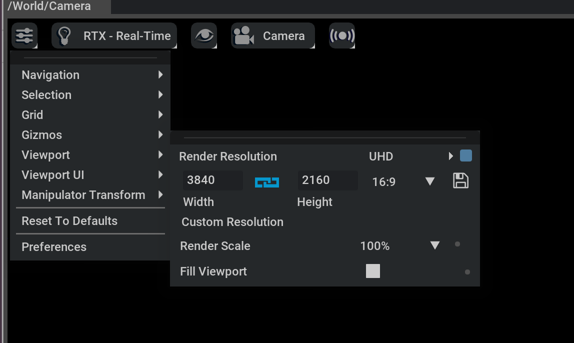
After launching your viewport, you can change the resolution using the menu in the top left and going to Viewport.
Note
When changing the resolution, Omniverse Kit only supports square pixels. This means that the resolution aspect ratio must be the same as the aperture ratio.