Robot Schema#
The Robot Schema extends OpenUSD definitions to define robotic structures. While currently experimental, it provides a standardized way to represent robots by building upon USD Common definitions and the Physics Schema for kinematic tree definitions.
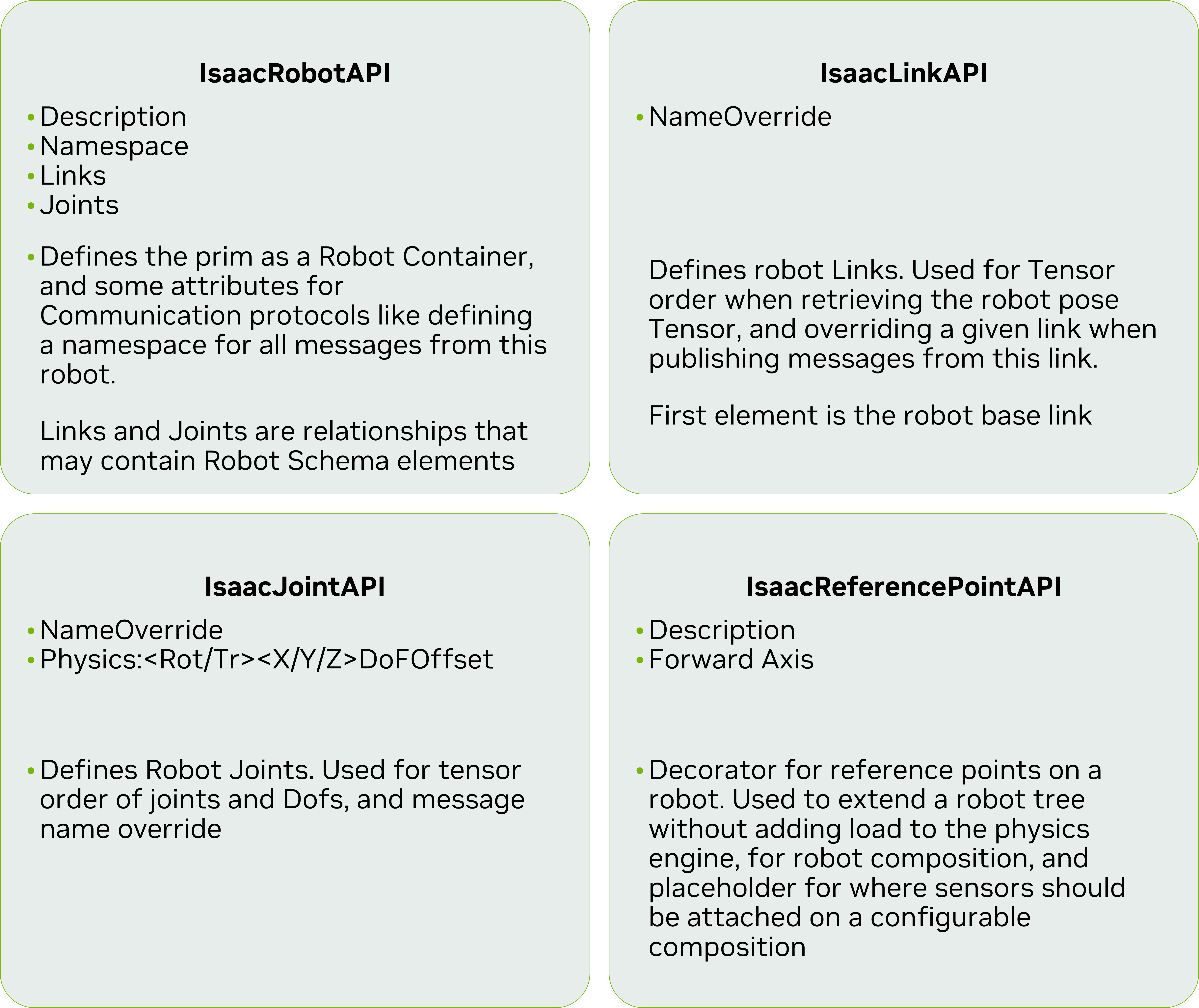
The schema defines four fundamental Structure Types:
Robot API#
The IsaacRobotAPI serves as the root definition for a robot, describing its complete composition. Applied to the robot’s root prim, it contains:
Description: Metadata describing the robot’s purpose and capabilities
Namespace: Unique identifier namespace for robot component messaging
Robot Links: Ordered list of constituent links, starting with the base link
Robot Joints: Ordered list of connecting joints
Note
The Links and Joints lists need only contain elements relevant for reporting. The full kinematic tree may contain additional unlisted elements.
Link API#
The Link API describes a single link in the robot and serve as a flag to indicate that the link should be included in the robot compostion. This schema should be applied to the bodies of the robot. It contains the following attributes:
Name Override: By default, Isaac sim will use the prim name as the link name when reporting the robot state. This attribute allows for a custom name to be used.
Links Are not limited to Rigid bodies, and could be applied to other types of simulation types, such as deformable bodies. Care must be taken when using links on deformable bodies, as it would require an equivalent way to compute the robot state, if needed.
All Links used by the robot must have a IsaacLinkAPI applied, regardless of wether they are included in the IsaacRobotAPI Links list or not.
Joint API#
The Joint API describes a single joint in the robot and serve as a flag to indicate that the joint should be included in the robot compostion. This schema should be applied to the joints of the robot. It contains the following attributes:
Name Override: By default, Isaac sim will use the prim name as the joint name when reporting the robot state. This attribute allows for a custom name to be used.
DOF (degree of Freedom) Offset: For each degree of freedom, we introduce an index offset to the reported state, so we can report all DOF stats as a single flat list. This is useful for composing robots that have multiple degrees of freedom, but share a common root joint. There is one attribute per degree of freedom axis. The default value is 0-6, depending on the axis. If the joint represents a single degree of freedom, this attribute can be ignored.
All Joints used by the robot must have a IsaacJointAPI applied, regardless of wether they are included in the IsaacRobotAPI Joints list or not.
Reference Point API#
The IsaacReferencePointAPI describes Points of interest on the robot, for example attachment points for tools or sensors. This schema should be applied to the points of interest of the robot. It contains the following attributes:
Description: A description of the reference point, for example “Tool Attachment Point” or “Sensor Location”.
Forward Axis: The axis that is considered to be the forward direction of the reference point (X, Y, Z)
Composing Robots#
Robot compositions can be created by applying the Robot API to each sub-robot’s root prim. The final assembly is achieved by either: - Adding a sub-robot’s root prim to the parent robot’s joints and links lists. - Selecting specific links and joints from sub-robots
Applying the Robot Schema#
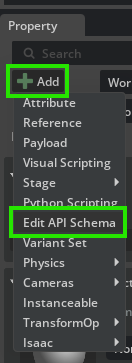
All robots in Isaac Sim’s library and imported through URDF Importer Extension and MJCF Importer Extension will have the Robot Schema applied to them. For robots imported in prior versions of Isaac Sim, the schema will need to be applied manually. To do so, select the root prim of the robot, and in the right panel under the Properties tab, check the + Add button, and select Edit API Schema
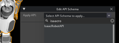
Then, Search for ‘RobotAPI’ and apply it to the root prim. Repeat for the other schemas at the appropriate Prims (IsaacLinkAPI, IsaacJointAPI, IsaacReferencePointAPI).
Properties for the Robot Schema will be displayed in the right panel under the Properties tab, their appropriate API Section, in Purple.
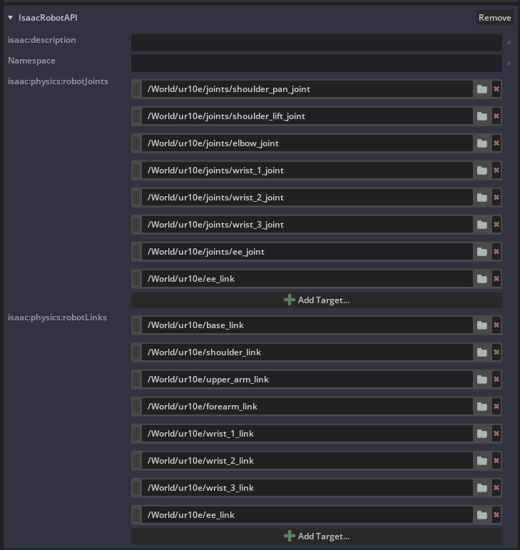
To Add new items to the Links and Joints list, click on the + Add Target button in the respective List, and on the selection menu, select the prim(s) to be added.
Applying the Robot Schema through code#
The following snippet shows how to apply the robot schema through code in existing assets that do not currently have it. Following the Asset Structure guidelines we recommend applying the schema through a Layer, so it remains separate from the robot base structure, and easier to be updated as the schema evolves. To use this script first open the asset you desire to add the schema to directly.
from pxr import Usd, UsdGeom, Sdf
import pxr
import omni.usd
import usd.schema.isaac.robot_schema as rs

stage = omni.usd.get_context().get_stage()
robot_asset_path = "/".join(stage.GetRootLayer().identifier.split("/")[:-1]) # Get the asset path from the stage
robot_asset = ".".join(stage.GetRootLayer().identifier.split("/")[-1].split(".")[:-1]) # Get the asset name from the stage
schema_asset =  f"configuration/{robot_asset}_robot_schema.usda"
edit_layer = Sdf.Layer.FindOrOpen(f"{robot_asset_path}/{schema_asset}")
if not edit_layer:
   edit_layer = Sdf.Layer.CreateNew(f"{robot_asset_path}/{schema_asset}")
# Add sublayer to the stage, but as a relative path
stage.GetRootLayer().subLayerPaths.append(schema_asset)
# Make all edits in the edit layer
with pxr.Usd.EditContext(stage, edit_layer):

   default_prim = stage.GetDefaultPrim()

   #Apply the Robot API to the default prim
   rs.ApplyRobotAPI(default_prim)

   #Get the relationships for the robot links and joints
   robot_links = default_prim.GetRelationship(rs.Relations.ROBOT_LINKS.name)
   robot_joints = default_prim.GetRelationship(rs.Relations.ROBOT_JOINTS.name)

   #Iterate over all the prims in the stage, and apply the Link API to the rigid body prims
   for prim in Usd.PrimRange(default_prim):

      #Apply the Link API to the rigid body prims
      if "PhysicsRigidBodyAPI" in prim.GetAppliedSchemas():
            rs.ApplyLinkAPI(prim)
            #Add the prim to the robot links relationship
            robot_links.AddTarget(prim.GetPath())

      #Apply the Joint API to the joints
      if prim.IsA(pxr.UsdPhysics.Joint):
            rs.ApplyJointAPI(prim)
            if not prim.IsA(pxr.UsdPhysics.FixedJoint):
               #Add the prim to the robot joints relationship
               robot_joints.AddTarget(prim.GetPath())

edit_layer.Save()
stage.Save()
Parsing Robot Structure#
The robot structure relies on the Physics Schema to define the robot kinematic tree. The robot schema extends the Physics Schema to include the robot composition information. To parse the robot structure, we need to first collect the Links and Joints that make up the robot, and then from The Robot API we start to build the robot structure from the first link on the Links list, Iterating over the joints based on their connection to the next links. The robot structure should be always a tree. Loops in the hierarchy need to be flagged with the “Exclude from Articulation” attribute in the joints, otherwise they will be arbitrarily broken during the parsing, based on the depth first search of the hierarchy. In the extension isaacsim.robot.schema we provide a set of utility scripts that parse the robot structure and outputs the Robot Kinematic tree based on the USD data.
Example#
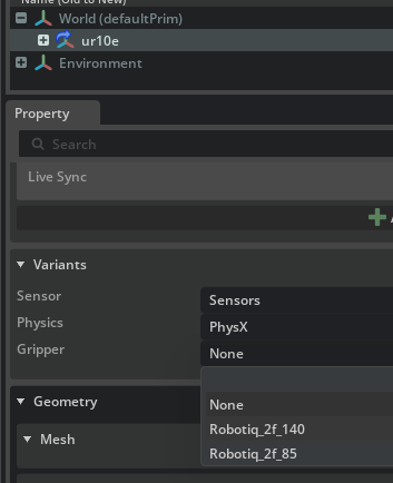
on the Content Browser, drag and drop a UR10e robot Robots/UniversalRobots/ur10e/ur10e.usd into the stage.
On the Variant selection menu at the properties panel, select the Robotiq 2f-140 gripper variant.
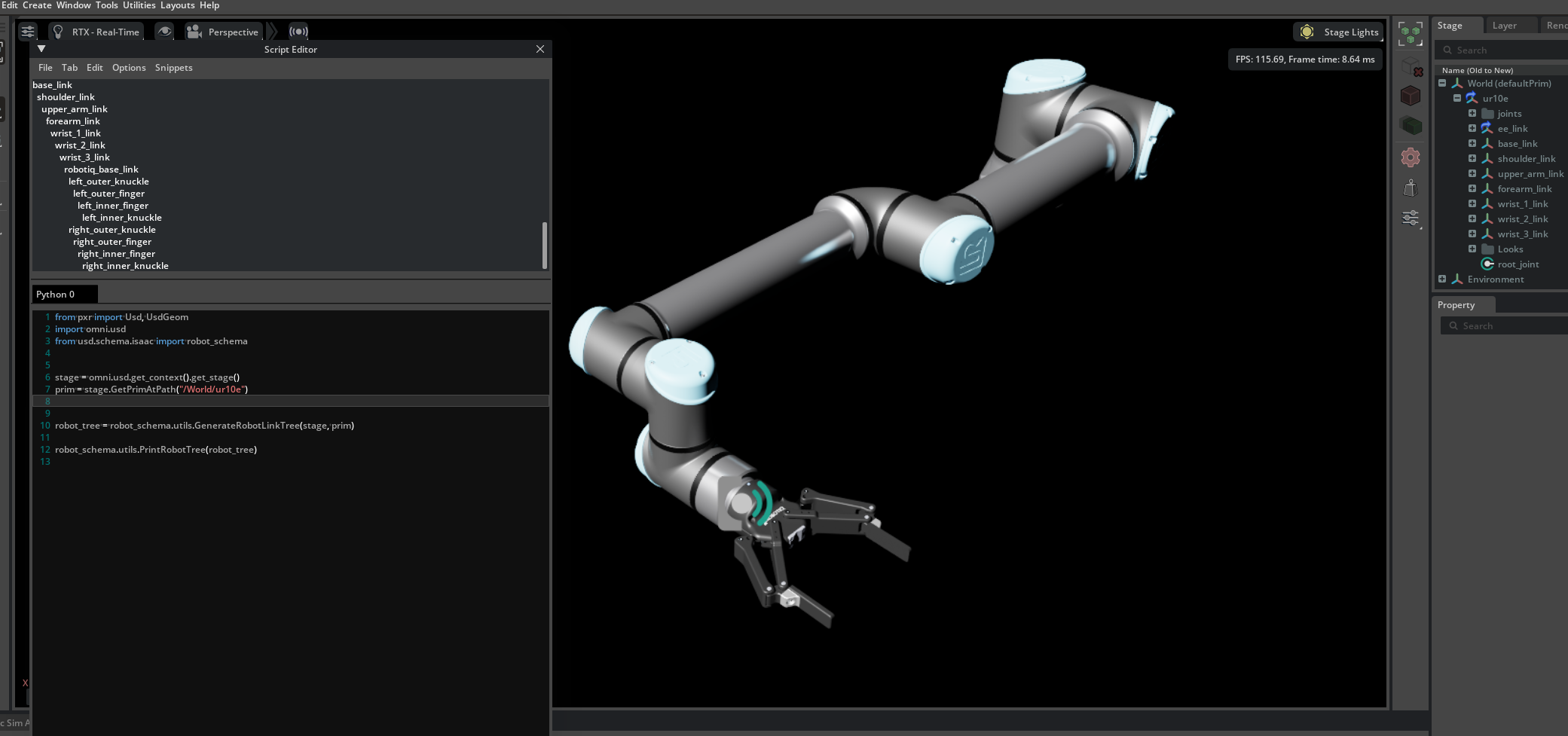
Open the Script Editor in Window > Script Editor, and run the following script:
from pxr import Usd, UsdGeom
import omni.usd
#For Legacy reasons, we need to import the schema from the usd.schema.isaac package
from usd.schema.isaac import robot_schema


stage = omni.usd.get_context().get_stage()
prim = stage.GetPrimAtPath("/World/ur10e")


robot_tree = robot_schema.utils.GenerateRobotLinkTree(stage, prim)

robot_schema.utils.PrintRobotTree(robot_tree)
On the console, you should see the following output:
base_link
   shoulder_link
      upper_arm_link
         forearm_link
            wrist_1_link
               wrist_2_link
                  wrist_3_link
                     robotiq_base_link
                        left_outer_knuckle
                           left_outer_finger
                           left_inner_finger
                              left_inner_knuckle
                        right_outer_knuckle
                           right_outer_finger
                           right_inner_finger
                              right_inner_knuckle
Note how the gripper is included in the robot structure, even though it is not part of the UR10e robot. Select the UR10e prim on the stage, and check how the Robot Lists have ee_link
Robot Schema Utility Functions#
GetAllRobotJoints(stage, robot_link_prim, parse_nested_robots): Returns all joints of a robot.GetAllRobotLinks(stage, robot_link_prim, include_reference_points): Returns all links of a robot.GetJointBodyRelationship(joint_prim, bodyIndex): Gets the target link for joint’s body connection, by index.GetJointPose(robot_prim, joint_prim): Returns joint pose in robot’s coordinate system.GetLinksFromJoint(root, joint_prim): Returns lists of links before/after specified joint.GenerateRobotLinkTree(stage, robot_link_prim): Generates tree structure of robot links.PrintRobotTree(root, indent): Prints visual representation of robot link tree.
Asset Structure#
Following the guidelines for Asset Structure, the recommended is to apply the schema on a separate layer, and load it as a sublayer on the robot asset.