URDF Importer Extension#
About#
Note
Starting from the Isaac Sim 2023.1.0 release, the URDF importer has been open-sourced. Source code and information for contributing can be found at our Github repository. As of Isaac sim 5.0, the former dedicated repository has been deprecated, and the code has been moved to the Isaac Sim repository.
The URDF Importer Extension is used to import URDF representations of robots. Unified Robot Description Format (URDF), is an XML format for representing a robot model in ROS.
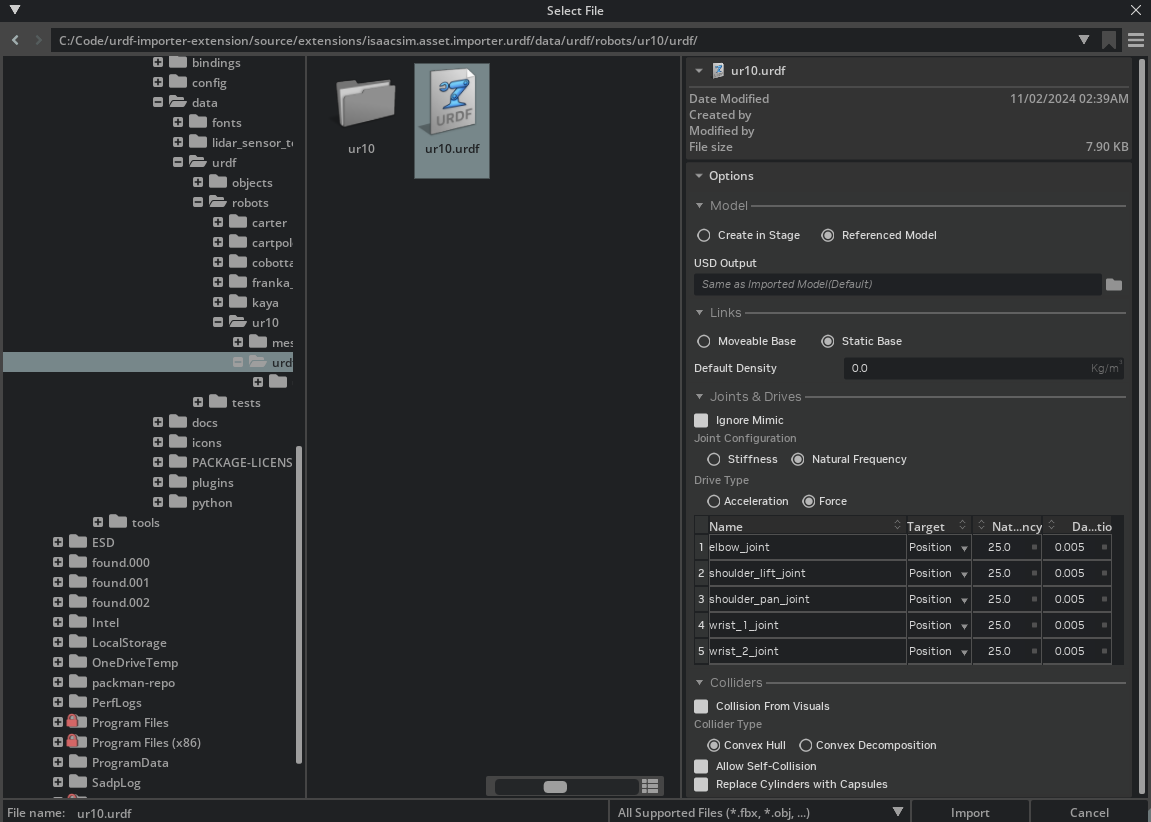
To Import URDF files, go to the top menu bar and click File > Import.
This extension is enabled by default. If it is ever disabled, it can be re-enabled from the Extension Manager
by searching for isaacsim.asset.importer.urdf.
Import results are logged in the Output Log, accessible from the bottom of the screen.
The Output Log will display any errors or warnings that occur during the import process. For more detailed log information directly open Isaac Sim’s log file, change the console to Info mode, or start Isaac sim with the parameter --verbose to display results in the terminal output.
Note
The Imported model follows the Isaac Sim Asset Structure convention, and the meshes are already instantiable to optimize performance.
Conventions#
Warning
To comply with USD prim name conventions, special characters in link, joint, mesh names, and all other reference asset filenames are not supported and will be replaced with an underscore. In the event that the name starts with an underscore due to the replacement, an a is pre-pended. It is recommended to make these name changes in the URDF directly.
See the Isaac Sim Conventions documentation for a complete list of NVIDIA Isaac Sim conventions.
Import Options#
Model#
Provides the Options to Import in Stage, or add as a referenced model. If Create in Stage is selected. Choose the options to Set as the default prim, and Clear Stage on Import. By default both are left unchecked.
Links#
Choose between a Moveable base (for example, a wheeled robot) or a Static base (for example, a 6-dof robotic arm). If the robot is a Moveable base, the base link will be set to moveable. If the robot is a Static base, the base link will be fixed in place with a root_joint.
The Default Density is used for links that do not have a mass specified in the URDF. If the density is set to 0, the physics engine will automatically compute the density with its default value.
Joints and Drives#
Provides an interface to configure individual joints, loaded with the default values.
Ignore Mimic#
If checked, the Mimic tag will be ignored on import. Otherwise joints with the mimic tag will receive the physx Mimic API, allowing it to work in tandem with the primary joint that is defined in its setup.
Joint Configuration#
Choose between configuring the joints directly through Stiffness or with Natural Frequency. Saved values will always be in Stiffness. - Stiffness: Edit the joint drive stiffness and damping directly.
Natural Frequency: Computes the Joint drive stiffness and Damping ratio based on the desired natural frequency using the formula:
where \(\omega_n\) is the natural frequency, \(\zeta\) is the damping ratio, and \(m\) is the total equivalent inertia at the joint. The damping ratio is such that \(\zeta = 1.0\) is a critically damped system, \(\zeta < 1.0\) is underdamped, and \(\zeta > 1.0\) is overdamped.
The Stiffness value is used to control the strength of the position drive. A combination of setting stiffness and damping on a drive will result in both targets being applied, this can be useful in position control to reduce vibrations.
Multi-Edit Edit: To Edit multiple joints at the same time, you can ctrl+click at their names, to select individual joints, or shift+click to select a range of joints. Once selected, the values will be applied to all selected joints.
Drive Type#
The drive type can be chosen between Acceleration and Force. Acceleration drives normalize the inertia before applying the effort, making it invariant to changes in robot mass (payload not included), equivalent to ideal damped actuator. In force drives, the effort is applied directly to the joint, equivalent to a spring-damper system.
Target#
Can be chosen between None, Position, and Velocity. If the drive type is set to position, the target will be the position in radians for revolute joints, or distance units for prismatic. For velocity drives, it’s the unit per second. When the joint is configured as Mimic you cannot change the Target Type.
Colliders#
Collision From Visuals: If checked, the collision objects will be created from the visual meshes when a collision object is not provided. Otherwise, no collision will be created for that link.
Collider Type: Select between Convex Hull or Convex Decomposition. Convex Hull will create a single convex hull around the collision mesh. Convex Decomposition will create multiple convex hulls around the collision mesh to better match the visual asset.
Allow self-collision: Enables self collision between adjacent links. It may cause instability if the collision meshes are intersecting at the joint.
Replace Cylinders with Capsules: When selected, cylinder colliders will be replaced with Capsule primitives.
Note
It is recommended that you set Self Collision to false unless you are certain that links on the robot are not self colliding
Note
You must have write access to the output directory used for import, it will default to the current open stage, change this as necessary.
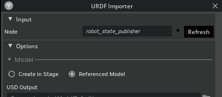
Importing URDF from a ROS 2 Node#
Enable the extension isaacsim.ros2.urdf to enable this feature. This will open a standalone URDF importer UI that allows to define a ROS 2 Node containing a robot description.
To select the appropriate node, type in the name of the node in the Node text box. If changes were made to the import settings, or to the published node hit Refresh. If the node name is in
Note
This feature is only available when the ROS 2 bridge is enabled.
For a detailed guide on how to use the ROS 2 URDF Importer, see the Import from ROS 2 Node Tutorial.
Robot Properties#
There might be many properties you want to tune on your robot. These properties can be spread across many different Schemas and APIs.
The general steps of getting and setting a parameter are:
Find which API is the parameter under. Most common ones can be found in the Pixar USD API.
Get the prim handle that the API is applied to. For example, Articulation and Drive APIs are applied to joints, and MassAPIs are applied to the rigid bodies.
Get the handle to the API. From there on, you can Get or Set the attributes associated with that API.
For example, if we want to set the wheel’s drive velocity and the actuators’ stiffness, find the DriveAPI:
 1# get handle to the Drive API for both wheels
 2left_wheel_drive = UsdPhysics.DriveAPI.Get(stage.GetPrimAtPath("/carter/chassis_link/left_wheel"), "angular")
 3right_wheel_drive = UsdPhysics.DriveAPI.Get(stage.GetPrimAtPath("/carter/chassis_link/right_wheel"), "angular")
 4
 5# Set the velocity drive target in degrees/second
 6left_wheel_drive.GetTargetVelocityAttr().Set(150)
 7right_wheel_drive.GetTargetVelocityAttr().Set(150)
 8
 9# Set the drive damping, which controls the strength of the velocity drive
10left_wheel_drive.GetDampingAttr().Set(15000)
11right_wheel_drive.GetDampingAttr().Set(15000)
12
13# Set the drive stiffness, which controls the strength of the position drive
14# In this case because we want to do velocity control this should be set to zero
15left_wheel_drive.GetStiffnessAttr().Set(0)
16right_wheel_drive.GetStiffnessAttr().Set(0)
Alternatively you can use the Omniverse Commands Tool Extension to change a value in the UI and get the associated Omniverse command that changes the property.
Note
The drive stiffness parameter should be set when using position control on a joint drive.
The drive damping parameter should be set when using velocity control on a joint drive.
A combination of setting stiffness and damping on a drive will result in both targets being applied, this can be useful in position control to reduce vibrations.
References#
Please refer to the Asset Structure for more information about the asset structure.
Examples#
For Usage examples, see the Tutorial: Import URDF .