Tutorial 8: Generate Robot Configuration File#
Learning Objectives#
This is the third manipulator tutorial in a series of four tutorials. This tutorial will show you how to generate the robot configuration file for the UR10e robot from Universal Robots and the 2F-140 gripper from Robotiq. These robot configuration files provides information about the robot’s kinematics, dynamics, and other properties that are used in RMPFlow, CuMotion, and Lula kinematics solvers.
30 Minutes Tutorial
Prerequisites#
Review Tutorial 7: Configure a Manipulator tutorial prior to beginning this tutorial, continue the following steps from the asset built in the previous tutorial.
Note
If you have not completed the previous tutorial, you can find the prebuilt asset in the content browser at Isaac Sim/Samples/Rigging/Manipulator/Configure_Manipulator/ur10e/ur/ur_gripper.usd.
Generate Robot URDF#
Generate the robot URDF file from the UR10e robot and the 2F-140 gripper.
Enable the Isaac Sim USD to URDF Exporter Extension#
Go to Window > Extensions.
Type URDF in the search box, and find the Isaac Sim USD to URDF Exporter Extension.
If you can’t find it, remove the @feature filter from the search box.
Enable the extension by clicking the toggle button labeled ENABLE.
Check the box for AUTOLOAD, just to the right of ENABLE.
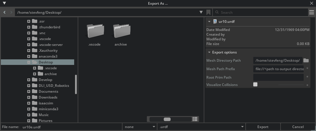
Export the URDF File#
Open the
ur_gripper.usdasset you made in the previous tutorial, or use the completed asset provided above.Click File > Export URDF.
In File name on the bottom left corner, save the file name to
ur_gripper.urdf.In the Mesh Directory Path field, select the correct folder path to save the URDF meshes.
Click Export.
Note
Learn more about the USD to URDF Exporter Extension in the USD to URDF Exporter Extension manual.
Generate Lula Robot Description Files and Collision Spheres#
Generate the Lula robot description files and collision spheres for the UR10e robot and the 2F-140 gripper.
Enable the Isaac Sim Lula Extension#
Go to Window > Extensions.
Type Lula in the search box, and find the Isaac Sim Lula Extension.
If you can’t find it, remove the @feature filter from the search box.
Enable the extension by clicking the toggle button labeled ENABLE.
Check the box for AUTOLOAD, just to the right of ENABLE.
Prepare the robot asset for Lula#
The lula robot description editor currently does not support instantiable meshes, so we need to prepare the robot asset for Lula by removing the instantiable meshes.
Open the
ur_gripper.usdasset you made in the previous tutorial, or use the completed asset provided above.Select all
visualsandcollisionsprims on the stage, on the property editor, uncheck the Instantiable fieldHint
You can use the search feature to find the
visualsandcollisionsprims by searching forvisualsandcollisionsrespectively.
Note
The completed asset for this tutorial can be found in the content browser at Isaac Sim/Samples/Rigging/Manipulator/configure_manipulator/ur10e/ur/ur_gripper_lula.usd.
Configure Joints in Lula Robot Description Editor#
Press PLAY to start the simulation.
Click Tools > Lula Robot Description Editor.
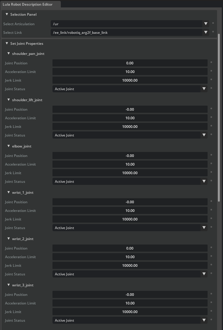
In the Selection Panel, select the ur articulation.
Go down to the Set Joint Properties section.
For each of the Universal Robots joints, set the Joint Status to Active Joint, keep the other settings as default.
Keep the Robotiq 2F-140 gripper joints as Fixed Joint, so the robotics controller will not attempt to move the gripper joints to optimize for the robot position.
Hint
The gripper and arm usually are controlled separately. Since lula framework does not actually control the gripper during collision checking, so cspace does not need to include the gripper joints.
Important
Do not stop the simulation, you will need it to generate the collision spheres.
Hint
Pay attention to the default values of the joints in cspace_to_urdf_rules.
They should be the same positions with the initial pose in the manipulator USD, or you need to reset the robot joint positions to these initial positions during task initialization.
Generate Collision Spheres#
Do not stop the simulation, or exit the Lula Robot Description Editor, or you will need to redo the previous steps.
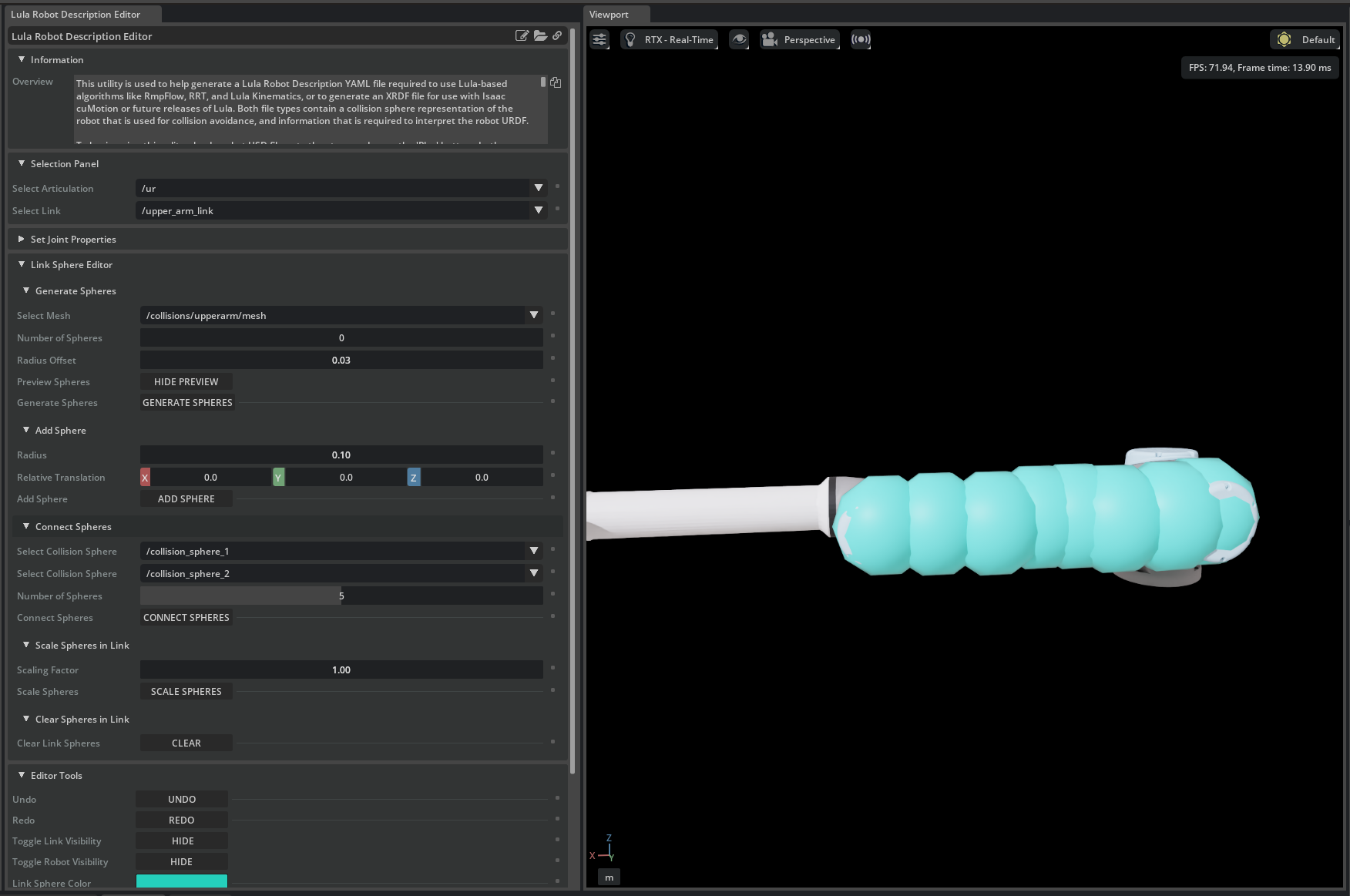
Go down to the Link Sphere editor section.
For each of the robot links that you want ot generate collision spheres for, in the Selection Panel/Select link, select the link. We will use upper_arm_link as an example.
In the Link Sphere editor/Generate Spheres/Select Mesh dropdown menu, select the mesh that the collision spheres are based on. For example, select
/collisions/upperarm/mesh.Set the Radius Offset to
0.03. This is the offset between the mesh radius and the collision sphere radius.Set the Number of Spheres to
8. This is the number of collision spheres to generate. Validate that you see 8 red spheres on the upper_arm_link.Optionally, adjust the Sphere Position by left clicking on the spheres and dragging them around.
Click Generate Spheres, the sphere will turn a cyan color to indicate that the collision spheres have been generated.
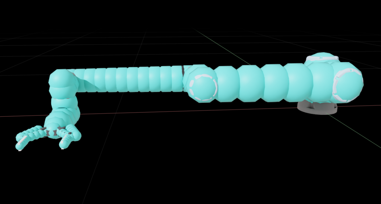
Repeat the same steps for all the other links in the ur articulation, including the gripper links.
Important
Do not stop the simulation, you will need it to generate the robot configuration file
Note
Verify that the completed asset looks like the following image:
Hint
The following suggestions can help you tune the collision spheres:
In general, make the collision spheres large enough to encompass the link, but not too large to cause solver issues.
When choosing the size and number of collision spheres, more collision spheres the more accurate the collision detection will be, but too many collision spheres will slow down the solver.
Unless you have specified collider meshes, there’s no restrictions to generate collision spheres on the collision meshes of the links only. If the visual mesh give you better collision mesh approximation, you can generate the collision spheres on the visual mesh.
For longer arm links, it is generally easier to use the method above to only generate collision spheres on the ends of the link, then use
Link Sphere editor/Generate Spheres/Add Spheresto add the collision spheres to the entire link evenly.If the sphere sizes are too small or too large, you can use
Link Sphere editor/Generate Spheres/Scale Spheres in Linkto scale the sphere sizes.The generate spheres utility is not guaranteed to work for all meshes. It only works for water-tight triangle meshes. If the automatic generator doesn’t work for a link, add the spheres and connect them by hand.
Export the Lula Robot Description File#
Do not stop the simulation or save the file, you need it to export the robot configuration file.
In the Lula Robot Description Editor, go to the very bottom and find the Export To File section.
Expand Export to Lula Robot Description File, click the file icon and specify the file name to
ur10e.yamlClick Save to export the robot configuration file
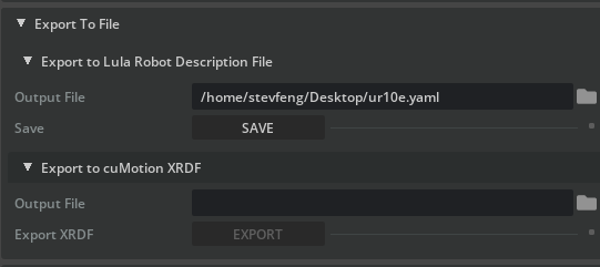
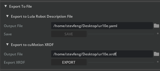
You can also export the cuMotion XRDF file by going to Export To File > Export to cuMotion XRDF and specify the file name to
ur10e.xrdf.Stop the simulation after the robot configuration files are exported
Note
See Lula Robot Description and XRDF Editor for more information on the robot description files.
Summary#
In this tutorial, you have learned how to generate the robot configuration file for the UR10e robot and the 2F-140 gripper using the Lula Robot Description and XRDF Editor and the USD to URDF Exporter Extension extensions.