Camera Placement#
Camera Placement Tool is a component of the isaacsim.sensors.rtx.placement extension, which aims at optimizing camera placement in a stage according to user customized requirements.
Open the Camera Placement Tool Panel#
The Camera Placement Tool is accessible by Tools > Sensors > Camera Placement.
Input Fields#
Camera Placement Output Path:
The folder path where the generated camera placement data will be saved.
The file camera_info_payload.json will be output to this folder, containing information about all cameras relevant to the current camera placement task
Cached data would include:
Camera Path
Camera Position
Focus Point Position
- Example
- Output: in
camera_info_payload.json
Total Camera Number: The total number of cameras to be placed in the scene.
Camera Range Parameters:
- Camera Height Range:
Define the allowable height range for camera placement above the ground.
- Camera Distance Range:
Set the distance range within which a camera can be placed from any point P on the stage.
- Ensures:
For any point P, there exists a camera C such that the distance between C and P is within this range.
- Camera Look Down Angle Range:
Define the downward tilt angle range for the cameras.
Zero degrees means the camera is parallel to the ground (horizontal view).
90 degrees means the camera is pointing straight down (top-down view, perpendicular to the ground).
Stage Processing Parameters:
- Patch Size:
The stage is divided into patches of this size for estimating coverage.
The smaller size means more detailed stage analysis when calculate camera coverage.
On the other hand, It also means more computation time.
- Ground Height:
Height of the ground surface in the stage.
Other Tuning Parameters:
- Border Checking Index:
Controls how close cameras can be placed to the boundary of the stage. Prevents invalid placements that can result from proximity to obstacles or being outside the stage bounds.
- Camera On Navmesh:
Whether cameras must be placed only on the navigation mesh.
- Minimum Coverage Increase:
The minimum additional patch a camera must cover for it to be considered valid. If the new camera increases coverage less than this value, placement will stop.
- Limit FOV by Distance:
Determines whether the camera’s field of view should be restricted based on its Camera Distance Range. - If enabled, the estimated camera coverage will be further limited according to the distance between each visible area and the target camera.
- Coverage Density:
Specifies how many cameras must cover each patch at a minimum.
- Target Coverage Ratio:
The desired overall ratio of the stage that must be covered by cameras according to the requirements. Placement stops if this target is not met.
Walkthrough#
Here is a walkthrough for using the Camera Placement Tool. Ensure the scene has valid navmesh baked before proceeding. The walkthrough uses the Isaac Sim Full Warehouse for demonstration.
Note
Stage unit must be in meters.
A valid NavMesh is required.
Z axis is up.
Step 1 - Enable the Extension#
Step 2 - Open the Target Stage#
Open the Isaac Sim Full Warehouse
Note
Verify that the navmesh is baked successfully
Access Window > Navigation > Navmesh and click on Bake button if you need to rebake the navmesh.
Before proceeding, ensure that the
omni.anim.navigation.bundle extensionis enabled according to instruction.
Step 3 - Configure Camera Placement#
In the Camera Placement section of the UI:
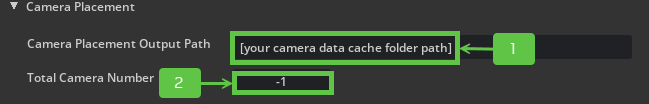
Set the Camera Placement Output Path, by entering your cache folder path
Set the Total Camera Number. Use -1 to auto-compute the minimum number of cameras needed.
Step 4 - (Optional) Adjust Camera Range#
If needed, configure the Camera Range Parameters such as height, look-down angles, and target distance. Refer to the Camera Range Input Fields for more details. This example uses the default values.
Step 5 - (Optional) Adjust Stage Processing#
Stage Processing Parameters allows user to config the camera placement method according to the stage’s size, height, and complexity. Tune Stage Processing Parameters to set patch size or ground height, if applicable. Refer to the Stage Processing Parameters Field for more details. This example uses the default values.
Step 6 - Fine-tune Placement#
Multiple configurable parameters have been added to help user check and refine the camera placement logic
In this case, we just need to modify these two parameter:
set Coverage Density to
2, which means for each patch in the stage, we need two cameras to cover it.set Target Coverage Ratio to
0.99, which means 99 percent of the patch need to be covered according to our set requirements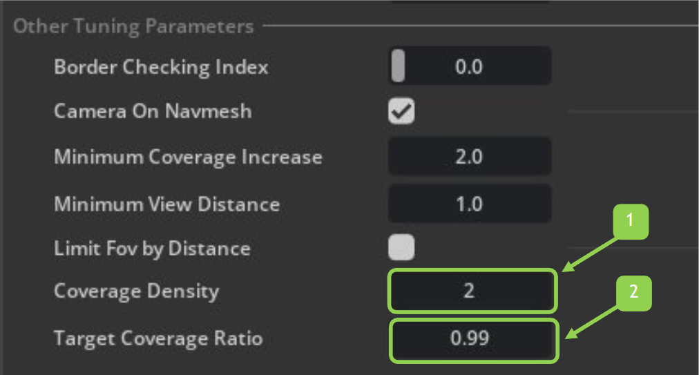
In this example, we are using the default values for other parameters
You are free to modify more Other Tuning Parameters to adjust placement logic if finer control is needed.
Refer to the Fine Tuning Parameters Field for more details.
Step 7 - Run Camera Placement#
The process can take some time to complete. The duration depends on the number of cameras to be placed and the complexity of the stage.
Step 8 - Check Coverage#
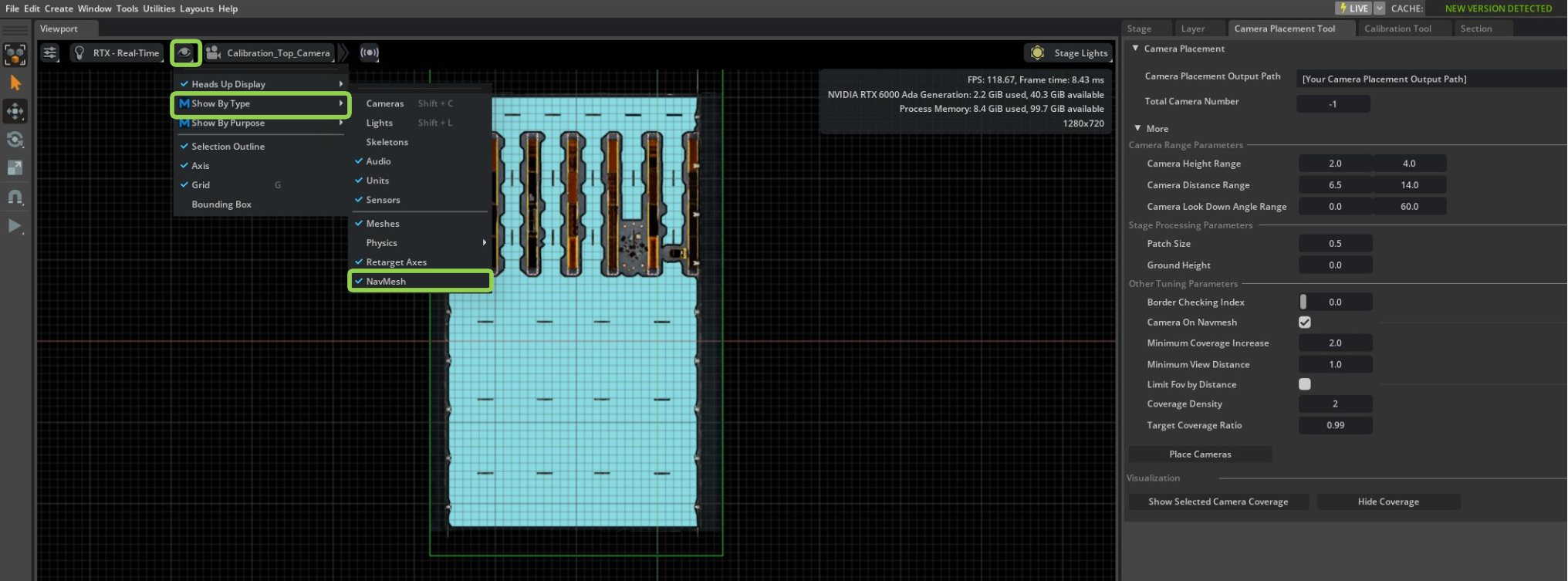
Get a top view of the stage to make the camera coverage visualization more clear.
Switch you view port camera to the created top view camera
Visualize Navmesh by clicking on Visibility Menu (eye icon on viewport) > Show By Type > Navmesh
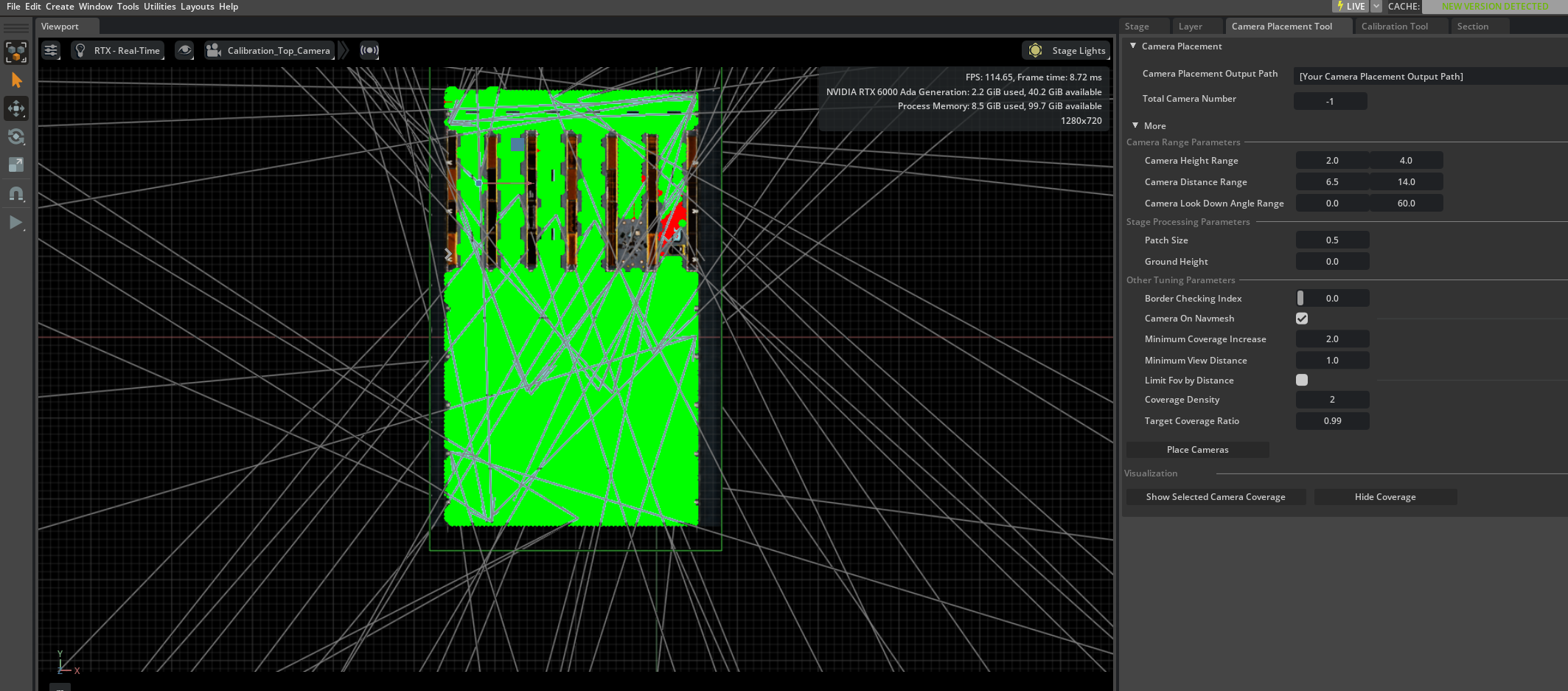
In the Stage tab select all camera prims under
World/Camerasprim.Return to the Camera Placement Tool panel and click Show Selected Camera Coverage to visualize the coverage of the selected cameras.
In this example, points covered once are shown in red, while points covered twice are shown in green.
From the visualization result, most points are covered as our expectation.
Step 9 - Hide Coverage#
Click the Hide Coverage button to remove the coverage overlay.
Step 10 - (Optional)Save Your Work#
Save/save as the updated USD file to preserve camera placements for further SDG workflows.