Running a Reinforcement Learning Policy through ROS2 and Isaac Sim#
Learning Objectives#
In this example, you learn to run a reinforcement learning policy through ROS2 and Isaac Sim. You will learn to:
Setup a ROS2 node to publish observations and receive actions from Isaac Sim for the H1 flat terrain locomotion policy
Setup Isaac Sim environment to run a reinforcement learning policy
Getting Started#
Prerequisite
The Pytorch package is required to run this sample. Please follow the Pytorch installation instructions to install the correct version for your system.
Enable the
isaacsim.ros2.bridgeExtension in the Extension Manager window by navigating to Window > Extensions.This tutorial requires the
h1_fullbody_controllerROS2 package which is provided in IsaacSim-ros_workspaces repo. Complete ROS 2 Installation to make sure the ROS 2 workspace environment is setup correctly.
Hint
If you encounter
error: externally-managed-environmentwhen installing Pytorch, try installing it in a virtual environment.If you encounter
ModuleNotFoundError: No module named 'yaml', please install PyYaml via pip.
Set Up Robot Joint Configurations#
First, follow the steps in Tutorial 13: Rigging a Legged Robot for Locomotion Policy to setup the robot joint configurations based on the locomotion policy parameter. This step is very important as mismatching the joint configurations can result in unexpected robot behavior.
Note
The H1 flat terrain policy environment definition file is available here
The angle units specified in the policy environment definition file are in radians. The Isaac Sim USD GUI interface expects the angles to be specified in degrees.
Hint
The rigged H1 robot is available in the content browser at Isaac/Samples/Rigging/H1/h1_rigged.usd.
Add IMU Sensor#
The IMU sensor is used to get the body frame linear acceleration, angular velocity, and orientation. The flat terrain policy requires the linear velocity, angular velocity, and gravity vector from the pelvis link, so we need to add an IMU sensor to the pelvis link to compute these values.
You can create an IMU sensor by right clicking on the
/h1/pelvisand select Create > Isaac > Sensors > Imu Sensor
Note
If you add the imu to a different link, e.g. the torso link, you will need to first transform the IMU data to the pelvis link frame before using it in the policy.
Set up ROS2 Node for the H1 Humanoid Robot#
The ROS2 node publishes the observations and receives the actions from Isaac Sim. As specified in the environment definition file, the observations requires the following information:
Body frame linear velocity
Body frame angular velocity
Body frame gravity vector
Command (linear and angular velocity)
Relative joint position
Relative joint velocity
Previous Action
We can obtain the body frame linear velocity, angular velocity, and gravity vector from processing the IMU data. The command is the desired linear and angular velocity of the robot, which can be retrieved from a ROS2 twist message. The relative joint position and velocity can be computed from the Isaac Sim joint state topic. The previous action is the action applied last iteration and can be tracked by the policy node.
The action is a joint state message, which is a dictionary of joint names and their desired positions.
In this section, we will setup omnigraph nodes that publishes the observations and receives the actions from Isaac Sim on physics step.
Create an on demand omnigraph#
First open the H1 unitree robot model that you rigged in the Tutorial 13: Rigging a Legged Robot for Locomotion Policy tutorial. Then create a scope to hold the ActionGraphs by right clicking on the stage and selecting Create > Scope, rename it “Graph”
Inside the Graph scope, right click and select Create > Visual Scripting > ActionGraph.
Rename the ActionGraphto “ROS_Imu”
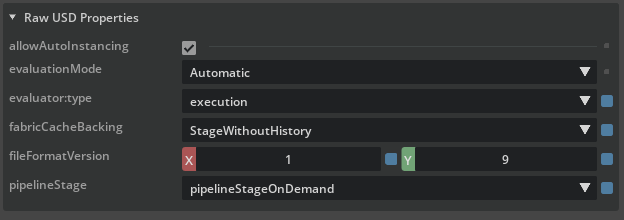
Left click on the ActionGraph node, scroll down in the property editor and set the
pipelineStagetopipelineStageOnDemand
This will ensure the ActionGraph node runs when the Isaac Sim physics steps.
Create Imu Publisher node#
This node publishes the IMU data to ROS2, which contains the body frame linear acceleration, angular velocity, and orientation.
Right click on the actionGraph node earlier and select Open Graph.
Copy the following nodes into the Action graph:
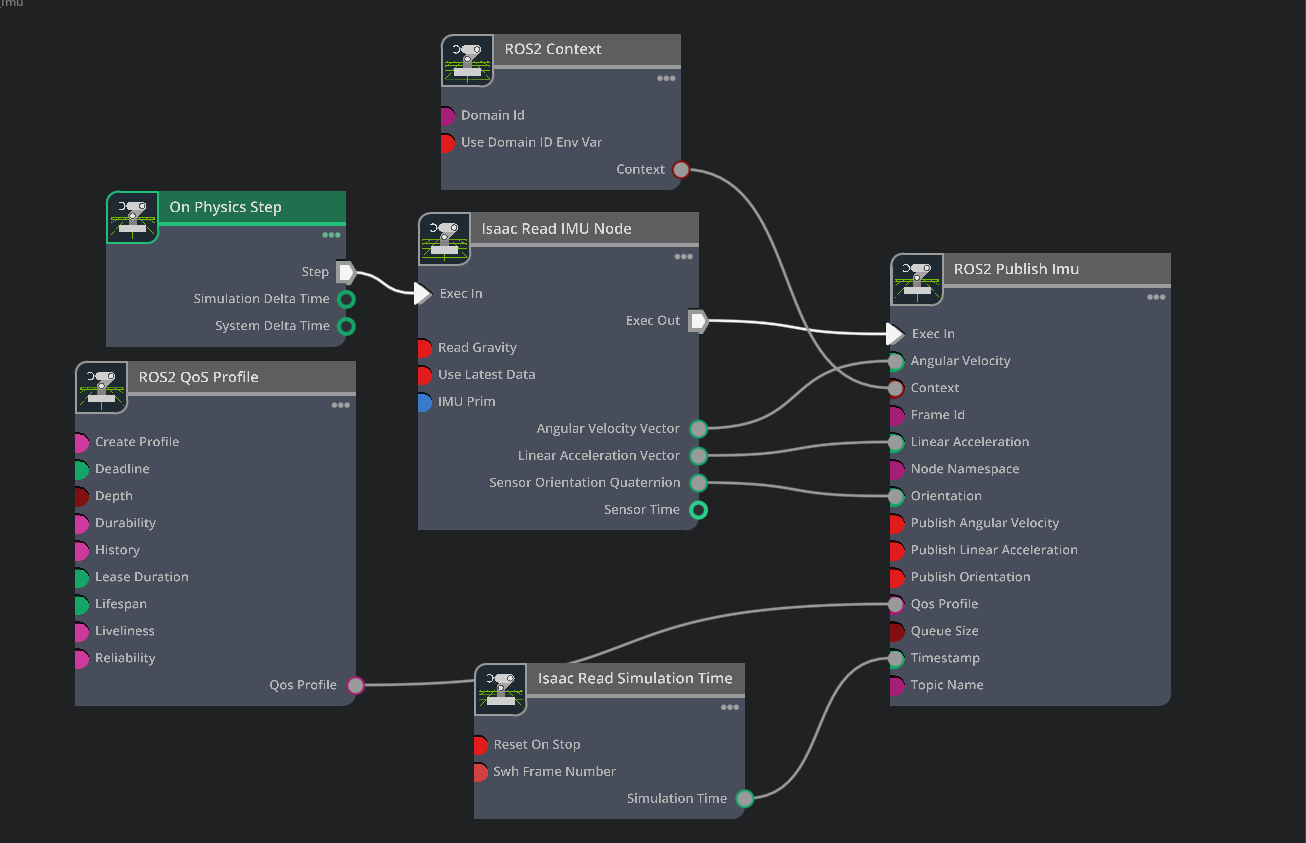
On Physics Step: This node is triggered when the Isaac Sim physics steps, and runs the entire graph.ROS2 Context: This node creates a context for the ROS2 node.ROS2 QoS Profile: This node sets the QoS profile for the ROS2 node.Isaac Read IMU Node: This node reads the IMU data from Isaac Sim.Isaac Read Simulation Time: This node reads the simulation time from Isaac Sim.ROS2 Publish IMU: This node publishes the IMU data to ROS2 using theIsaac Read IMU NodeandIsaac Read Simulation Timenodes as source.
Connect the nodes as shown in the image below.
Set the
Isaac Read IMU NodeinputIMU Primto/h1/pelvis/Imu_Sensorto read the IMU sensor dataUncheck input
Read Gravityof theIsaac Read IMU Nodeto avoid reading the gravity vector from the pelvis link. This is because we only want the linear and angular velocity from the pelvis link.Check the
Reset on Stopinput ofRead Simulation Timenode to reset the simulation time when the simulation stops.
Create joint state publisher and subscriber nodes#
This node publishes the joint states to ROS2, which contains the joint names, positions, and velocities, and subscribes to the joint state commands from Isaac Sim.
Create a new ActionGraph node and rename it to “ROS_Joint_States”
Set the
pipelineStagetopipelineStageOnDemandCopy the following nodes into the Action graph:
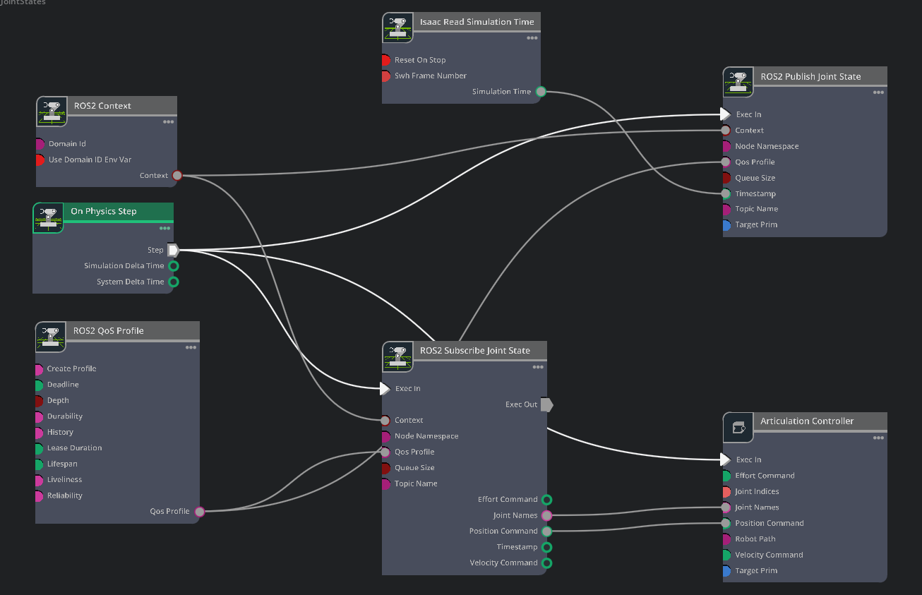
On Physics Step: This node is triggered when the Isaac Sim physics steps, and runs the entire graph.ROS2 Context: This node creates a context for the ROS2 node.ROS2 QoS Profile: This node sets the QoS profile for the ROS2 node.ROS2 Subscribe Joint State: This node subscribes to the joint states commands from the external policy node.ROS2 Publish Joint State: This node publishes the current joint states to ROS2 from Isaac SimIsaac Read Simulation Time: This node reads the simulation time from Isaac Sim.Articulation Controller: This node will execute the joint state commands from the Subscribe joint States node
Connect the nodes as shown in the image below.
Set the
ROS2 Publish Joint StateinputTarget Primto/h1, andTopic Nameto/joint_statesSet the
ROS2 Subscribe Joint StateinputTopic Nameto/joint_commandSet the
Articulation ControllerinputTarget Primto/h1Check the
Reset on Stopinput ofRead Simulation Timenode to reset the simulation time when the simulation stops
Note
The completed asset is available in the content browser at Isaac Sim/Samples/ROS2/Robots/h1_ROS.usd.
Publish ROS clock and set up environment#
Now the asset is set up, we will create a simulation scenario to place the robot, configure the physics settings, and ROS time publish
Setup Simulation Scenario#
Create a new file, in the Content Browser, go to
Isaac Sim/Environments/Simple_Warehouseand drag thewarehouse.usdasset into the stageDrag and drop the
h1_ROS.usdasset that you made earlier into the stage. Set the Z transform to1.0so it is above the ground.Create a
Physics Sceneby right clicking on the stage and selecting Create > Physics > Physcis SceneSelect the
Physics Sceneand setTime Steps Per Secondto200Since we only have one robot, we want to use CPU physics for better performance.
Uncheck
Enable GPU DynamicsSet the
Broadphase TypetoMBP
Setup ROS2 Clock Publisher#
Create a new ActionGraph node and rename it to “ROS_Clock”
Set the
pipelineStagetopipelineStageOnDemandCopy the following nodes into the Action graph:
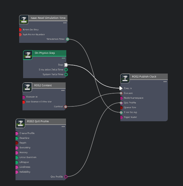
On Physics Step: This node is triggered when the Isaac Sim physics steps, and runs the entire graph.ROS2 Context: This node creates a context for the ROS2 node.ROS2 QoS Profile: This node sets the QoS profile for the ROS2 node.ROS2 Publish Clock: This node publishes the ROS2 clock to ROS2Read Simulation Time: This node reads the simulation time from Isaac Sim
Connect the nodes as shown in the image below.
Check the
Reset on Stopinput ofRead Simulation Timenode to reset the simulation time when the simulation stops.
Note
The completed environment is available in the content browser at Isaac Sim/Samples/ROS2/Scenario/h1_ros_locomotion_policy_tutorial.usd.
Run ROS2 Policy#
Now the asset is set up, you can run the ROS2 policy. First build the ROS 2 workspace and source the setup.bash file.
Launch the
h1_fullbody_controllerROS2 package by running the following command in the environment with Pytorch installed:ros2 launch h1_fullbody_controller h1_fullbody_controller.launch.py
Note
This ROS2 package computes observations and actions using the ROS messages that we are publishing above and the flat terrain locomotion policy. When no command velocities are received, the robot will stand still and maintain balance. Make sure to start the ROS2 policy before starting the simulation, otherwise the robot will fall over.
Open the H1 scenario you created earlier and press PLAY to start the simulation.
In a separate terminal, source ROS and launch
teleop_twist_keyboardor another desired package to publish Twist messages:ros2 run teleop_twist_keyboard teleop_twist_keyboard
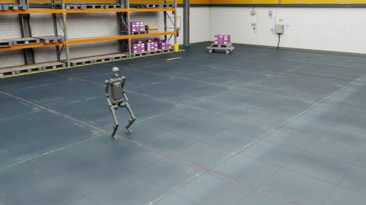
You can now control the H1 humanoid robot using your keyboard. Try the controls and see if the robot moves as expected.
Forward:
iForward + Turn Left:
uForward + Turn Right:
oTurn Left:
jTurn Right:
lStand Still:
k
Important
Moving backwards is not supported in this version of the policy. Pressing
m,,,.key will cause the robot to fall over.Setting linear and angular velocity above 0.75 exceeds the velocity limits of the policy and will cause the robot to fall over.
The robot may drift overtime when there’s no command velocities. This is expected behavior.
Summary#
This tutorial covered:
Creating and setting up an ROS2 node to publish observations and receive actions from Isaac Sim for the H1 flat terrain locomotion policy
Setting up Isaac Sim environment to run a reinforcement learning policy
Next Steps#
Learn more about Isaac Lab here and the Isaac Sim native method for policy deployment.