Tutorial 2: Assemble a Simple Robot#
This tutorial guides you through the basic GUI functions that add objects to the stage. It also introduces inspecting and modifying their physics and material properties.
Learning Objectives#
This tutorial covers how to:
Add and manipulate simple shapes
Enable physics properties in objects
Examine collision properties
Edit physics properties such as friction
Edit material properties such as color and reflectivity
Prerequisites#
Complete Tutorial 1: Stage Setup prior to beginning this tutorial.
Adding Objects to the Scene#
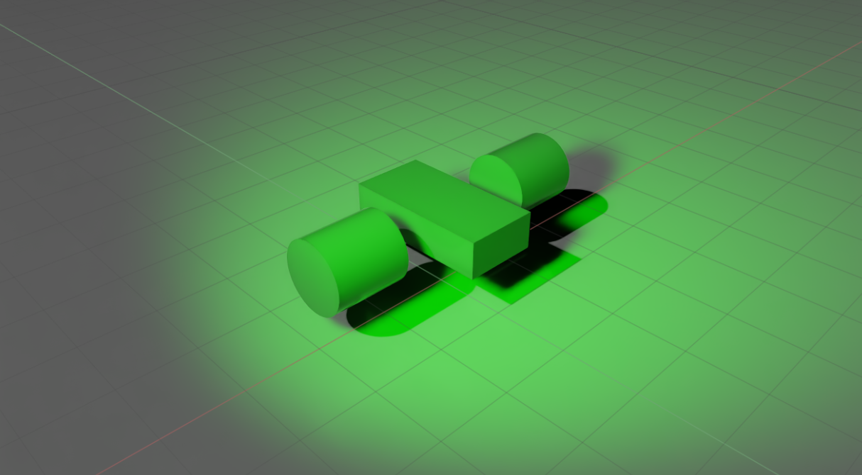
There are many ways to “add objects” to the stage, but all of them fundamentally do the same thing, which is to define a USD primitive in the stage context tree. The goal is to create a simple, two wheeled robot. Start by creating some simple shapes and modifying their properties. For the body, use a cube and for the wheels use cylinders.
To create the body of the robot:
Create an Xform by right clicking on the stage, selecting Create > Xform.
Rename it to body by right clicking on it and selecting Rename.
Fix the translation of the Xform to
(0, 0, 1)by clicking on the Translate section in the property panel and setting the X to0, Y to0, and Z to1.Create a cube clicking Create > Shape > Cube in the top menu bar. You should see the cube and the Move gizmo (the red, blue, and green arrows) appear in the viewport window
Click and drag on the blue arrow to raise the cube above the ground plane.
On the left side of the app, click the Scale icon (or press the R key while the cube is selected) to activate the scale widget.
Click and drag on the red part of the widget to scale the cube in the x direction
Place the cube in a specific location. Navigate to Transform > Scale in the property pane, and set the scale to
(1, 2, 0.5).Drag the cube to the Body Xform.
To create the wheels of the robot:
Create a Xform by right clicking on the stage, selecting Create > Xform. Set the Translate to
(1.5, 0, 1)and the Orient to90, 0, 0to rotate the wheel xform 90 degrees around the x axis.Rename it to wheel_left by right clicking on it and selecting Rename.
Create a cylinder by clicking Create > Shape > Cylinder in the top menu bar.
In the property panel on the bottom right corner, scroll down to the Geometry section. Change its Radius to
0.5and Height to1.0.Drag the cylinder to the wheel_left Xform.
Rename the cylinder to wheel_left by right clicking on it and selecting Rename.
Duplicate the wheel_left by right clicking the wheel_left xform on the stage tree, select Duplicate, and move it to
x = -1.5while keeping all other parameters the same.Rename the duplicated xform to wheel_right by right clicking on it and selecting Rename.
Rename the duplicated cylinder to wheel_right by right clicking on it and selecting Rename.
Adding Physics Properties#
The cubes and cylinders added so far are strictly visual prims, with no physics or collision properties attached to them. When you start the simulation by pressing Play and gravity is applied, these objects do not move because they are unaffected by physics.
To make the robot have physics, turn it into a rigid body with collision properties:
Select the Cube and both Cylinders on the stage tree by clicking while holding down the
Ctrl + Shiftkey to select each object, or justShiftif they are consecutively listed on the tree.In the Property tab, click on the
+ Addbutton.Select Physics > Rigid Body with Colliders Preset.
Press Play and verify that all three objects fall to the ground.
Rigid Body with Colliders Preset automatically adds the Rigid Body API and the Collision API to the objects. These two APIs can be applied separately because you can have objects that:
have mass and are affected by gravity, but have no collision properties so you can pass through them
can be run into but hang in the air and are not affected by gravity
To validate, add, or remove APIs assigned to the selected object:
Go to its Property tab, and scroll down to find sections labeled Rigid Body and Collider.
To add the APIs separately, find them under the same + Add button.
To remove APIs, click on the
Xto delete the section.
Hint
Dynamic objects can only select from Convex Hull, Convex Decomposition, Sphere Approximation, SDF mesh(gpu backend only) for collision shapes. Triangle mesh collision shapes are only available for static objects.

Examine Collision Meshes#
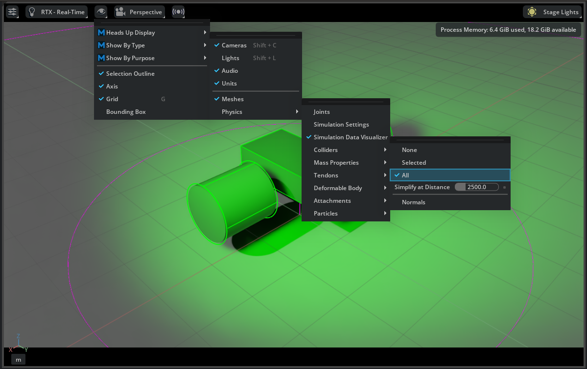
To visually examine the outlines of collision meshes for the objects:
Find the eye icon on top of the viewport.
Click Show By Type > Physics > Colliders > All.
Verify that purple outlines show up surrounding any objects that have collision APIs applied. For example, verify that it is the cuboid, the cylinders, and the ground plane.
Adding Contact and Friction Parameters#
For modifying frictional properties, you must create a different physics material and then assign it to the desired object.
Go to the Menu Bar and click Create > Physics > Physics Material.
Select Rigid Body Material in the popup box. A new
PhysicsMaterialappears on the stage tree.Tune the parameters such as friction coefficients and restitution in its property tab.
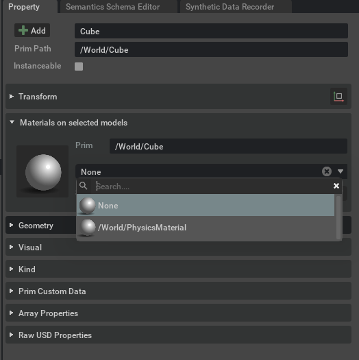
To apply the assigned physics material to an object:
Select the object in the stage tree.
Find the menu item Materials on Selected Model in the Property tab.
Select the desired material in the drop-down menu.
Material Properties#
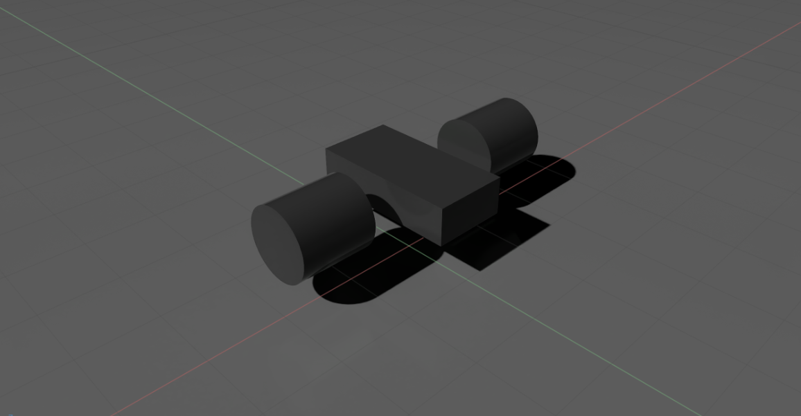
The objects may reflect the color of the spotlight added earlier, but it doesn’t actually have any colors assigned. You can confirm this by turning off the spotlight.
To change the color of the object, create a different material and then assign it to the objects, just like with the physics materials. For example, create two different materials, one for the body of the car and one for the wheels.
Click Create -> Materials -> OmniPBR twice.
Right-click on the newly added materials on the stage tree and rename them to body and wheel.
Assign the corresponding rigid bodies to the newly created materials by going to the Materials on selected models item in its Property tab, and select the matching material from the dropdown.
Change the property of the new materials. Select one of them on the stage tree, change its base color in Material and Shader/Albedo and play with its reflectivity roughness and whatever else you find interesting.
Verify that you see the color of the corresponding parts on the car change accordingly.
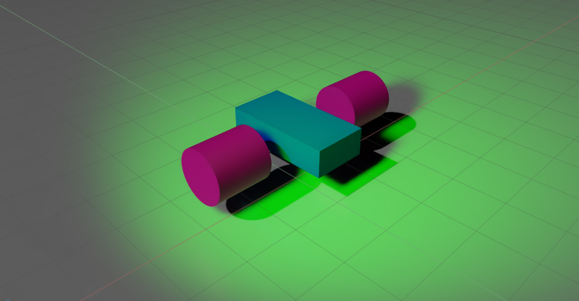
Checkpoint#
By the end of this tutorial, you should have a robot with a body and two wheels, similar to the mock_robot_no_joints asset, located in the Samples > Rigging > MockRobot folder.
Summary#
This tutorial explained how to add and manipulate object properties in the GUI, including:
Adding primitive shapes onto the Stage.
Editing material properties, physics properties, and collision properties.
Next Steps#
Continue to Working with USD to learn how to save your world and load assets in USD format inside Isaac Sim.
Go to Tutorial 3: Articulate a Simple Robot to learn how to turn these geometries into a moving car.